
Unassembled,buyer need to assemble by themselves.
Package include:
2x920KV CW Brushless Motor
2x920KV CCW Brushless Motor
4x30A Brushless ESC
2X8443 8.4*4.3" Carbon Fiber Propeller Self-locking Props
1XMK KK Multi-Copter Power Battery to 8 ESC Connection Board
1XAPM 2.8 Flight control
1x6M GPS with Compass
1x5pcs 10cm Servo Receiver Extension Lead Wire Cable
1xGPS Folding Antenna Mount Holder
12x3.5mm banana plug
1xDeans Style T Plug Male Connector Silicone Wire With 11.5CM 14awg
1xHook and & Loop Fastening Tape
1x11.1V 3300Mah 25C lipo battery

Two colors for choose,please tell us which one you prefer in advance,or we will ship it according to our inventory,thanks.
Features:
Multiple function remote control system,including helicopter,airplane and slider three type flying machine and five models,cover almost every popular model,you can fly any model by this radio.
3.5 inch colorful screen 320×480 resolution,clear display menu and graphs.
Great control distance: 1.1km on the ground,2km in the sky.
Expansion feedback module,users can get plane details in real time.
Make very setting clear and exactly output result.
Fast response time only 3ms to the operation,faster then the other transmitter 20ms,even ten channels also let you feel it.
High channel resolution reaches 4096,0.25us per resolution let all the servos keep tranquil.
Strong anti-jumping,DSSS(Direct sequence spread spectrum) technology.
Unbelievable price, high quality as supper bland, and more exactly, faster response, higher resolution,one and the only one anti-jumping DSSS technology.really worthy to have it.


Technical Parameter:
1. Dimension:18×9.5×22cm;
2. Weight:0.95kg;
3. Frequency:2.4GHz ISM band(2400MHz~2485MHz);
4. Modulation mode:QSPK;
5. Channel bandwidth:5.0MHz;
6. Spread spectrum:DSSS;
7. Adjacent channel rejection:>38dBM;
8. Transmitter power: <100mW(PCB testing),
<20dBm(3 meter air testing);
9. Operating Voltage:8.6~15V;
10. Operating Current:<95mA;
11. Control distance:800 meters ground;
12. Channel:10 Channel,8~10 channel are customizable;
13. Compatible model: Include all 120 degree and 90 degree swashplate helicopter,all fix wing and glider,five flying model;
14. Simulator model:under the simulator model the transmitter action turn off,change to power saving model;
15. Screen:16 colorful screen,size 78×52mm,320*480 pixel.
Before you can configure your APM,
you will need to first connect everything together.
This guide will show you all the cables and parts that you will need to connect to your APM.
Typical Quadcopter Layout
Please note the illustration Below highlights a (TYPICAL) installation. It contains optional equipment including a Camera Gimbal and a Battery Monitor and it utilizes an ESC wired "Y" power connection rather than the power distribution board common to many MultiCopters.

1. Connecting your motors and RC gear
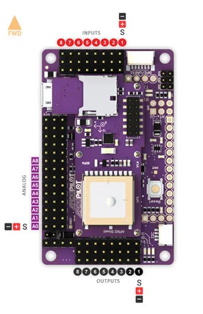
Overview of connections on the Ardupilot Mega v2 board
|
Note: the instructions below are for regular RC receivers with PWM output (one cable per channel). If you're using a "PPM" receiver (one cable carries all channels), follow the instructions .
Before you can configure your Arducopter, you will need to first connect everything together. This is quite easy. You need to connect your RC receiver to the Input side of the board. You can use the cables included with your Arducopter Kit, or if you are using another frame, you can use jumper cables, or female to female servo cables 
Connections between RC receiver and Ardupilot Mega v2 board
|
|
If you are using female to female servo cables, the ground (black) side of each connector must be on the outside for the board, the signal (white/orange) needs to be on the inside as shown below.
|
If you are using a multi-pin connector that was included with your Arducopter Kit, connect them as shown below
|


Please note, that your ESC, connectors should be plugged in the the output side, it is suggested that you only use power from one of your ESC's. This can be dune by cutting the red wire on all but one of the ESC's, or by using a special adaptor.
2. Connecting ArduCopter motors
|
Once again if you are using an Arducopter Kit, with the PDB, then you dont need to worry about this if you soldered everything correctly as the motors are assigned to the correct pins with the cables you plugged connected in the previous step. However you will neet to make sure your motors are spinning in the correct direction. The images below show the possible arducopter configurations with correct motor orientation
|
Quick Tip: If your motor is not spinning in the correct direction, simply switch the position of any two of the ESC-motor wires.
|
Arducopter Quad

|
Arducopter Tri

|
Arducopter Hexa, Octa, and Y6

|
Arducopter OCTA QUAD (X8)

|
Connecting a Roll-Tilt Camera mount

3. Connecting Optional Sensors
|
|
3. Connecting Optional Sensors
Sonar - Ultrasonic Rangefinder
AC2 supports the MaxSonar line of sonars for low level altitude hold and in the future collision avoidance. Below 10 meters sonar is primarily used for altitude hold. Above 10 meters, the barometric sensor is used. GPS is not required for altitude hold.
 Connect your Ultrasonic Sensor to the A0 port of your Ardupilot Mega v2 board
The sonar sensors are quite sensitive to noise, adding something like a ferrite choke to your cable could help. The most important is to mount your sonar away from other electronics like ESC, or wireless telemetry modules.
Possible Causes of sonar Interferance
- Electrical noise caused by ESCs, Servos, or switching BEC's on the same circuit as the Sonar
- EMF radiation from motors, motor wires, ESC's or Xbee.
- Acoustic noise from propellers
- Vibration from motors, props, etc.
|
AC2 supports the MaxSonar line of sonars for low level altitude hold and in the future collision avoidance. Below 10 meters sonar is primarily used for altitude hold. Above 10 meters, the barometric sensor is used. GPS is not required for altitude hold.
Connect your Ultrasonic Sensor to the A0 port of your Ardupilot Mega v2 board
|
The sonar sensors are quite sensitive to noise, adding something like a ferrite choke to your cable could help. The most important is to mount your sonar away from other electronics like ESC, or wireless telemetry modules.
Possible Causes of sonar Interferance
|
Optical Flow Sensor
 The optical flow sensor is used to improve the position hold accuracy of your arducopter. This sensor is supported from Arducopter 2.6 and above.
Connecting the optical flow sensor to APMv2
The optical flow sensor is used to improve the position hold accuracy of your arducopter. This sensor is supported from Arducopter 2.6 and above.
Connecting the optical flow sensor to APMv2
- Power, GND, NCS pins should be attached to A3
- MISO, MOSI and SCLK pins should be directly soldered to the pins shown above
- Default mounting is lens pointing down, pins forward
 Its a good idea to secure the wires with some cable ties so they dont break off over time

|
The optical flow sensor is used to improve the position hold accuracy of your arducopter. This sensor is supported from Arducopter 2.6 and above.
Connecting the optical flow sensor to APMv2
|
Its a good idea to secure the wires with some cable ties so they dont break off over time
|

