
We are professional industrial&electronic Categorie manufacturers in China. We have been working in this field for almost 10 years!
Our products include all kits&welded products for Andruino, Raspberry Pi, or mini flights.
If you have any needs, pls contcact us for free, we will help you get all things you need.
Thank you !
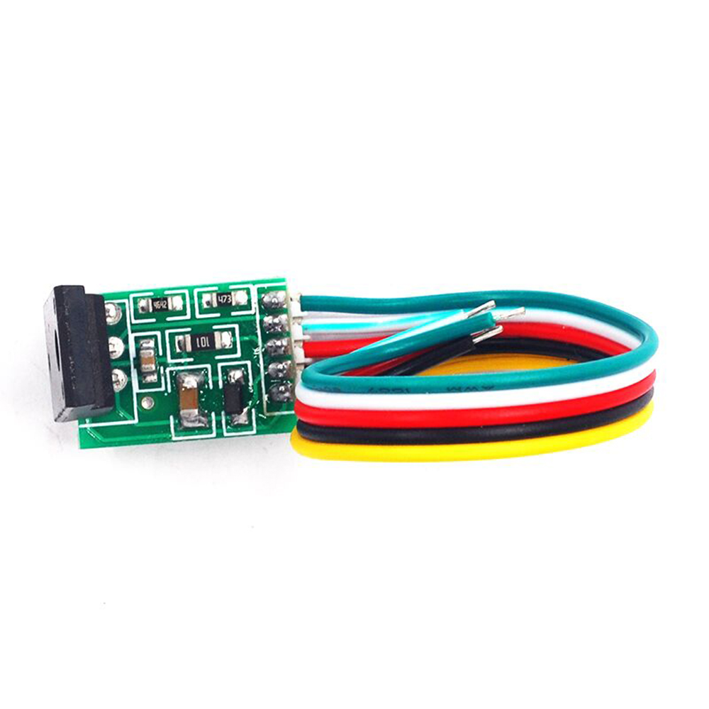
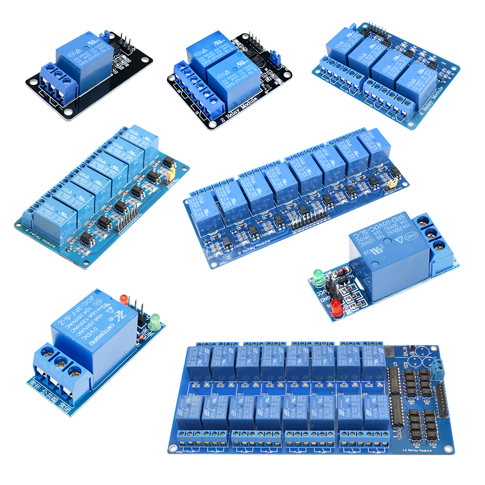
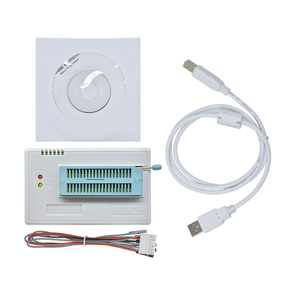
Product View


Product Details
Features:
1. Using high-quality materials, the quality is guaranteed
2. Easy to use, good stability
3. Small and exquisite size
4. Beautiful appearance
5. Wide application
1. Using high-quality materials, the quality is guaranteed
2. Easy to use, good stability
3. Small and exquisite size
4. Beautiful appearance
5. Wide application
USE:
The damage to the power board of the LCD display occupies a large proportion. Among them, power driver chips, high-power power switch tubes, sampling resistors, etc. are the most common damages. Due to the variety and variety of these components, they often cannot be repaired due to the lack of the same spare parts.
The LCD universal power supply module has the advantages of simple wiring, convenient installation, saving time, and improving the success rate of maintenance.
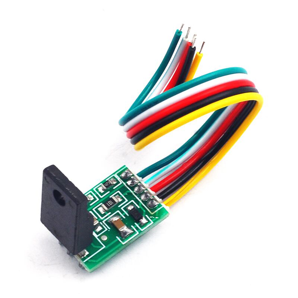
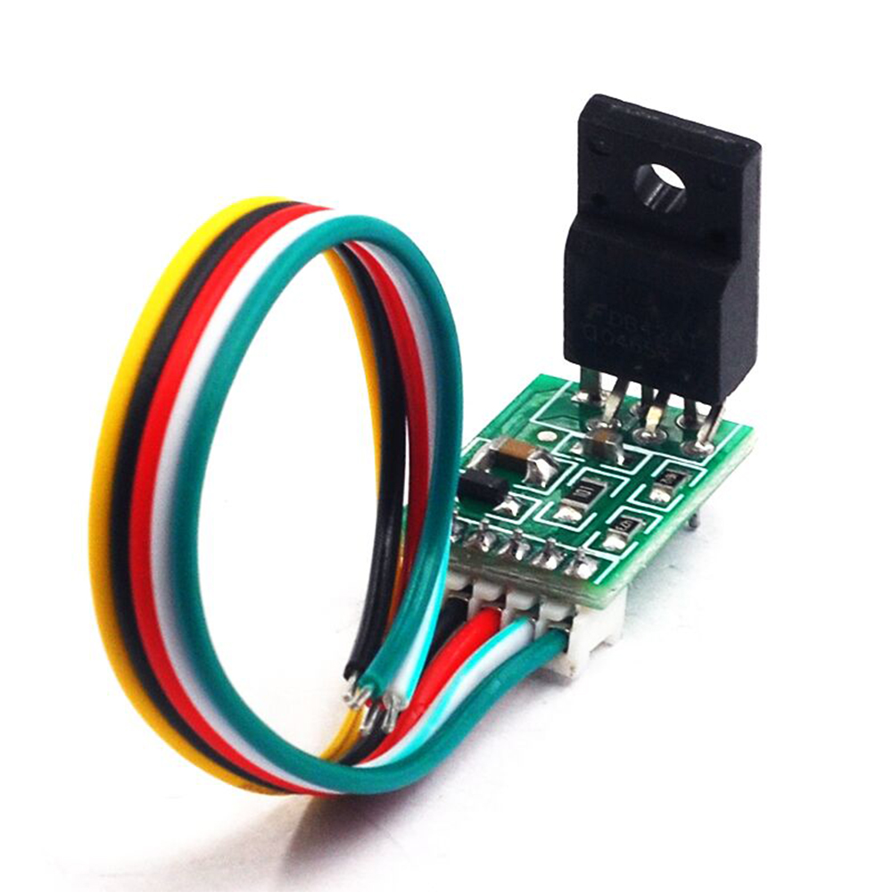
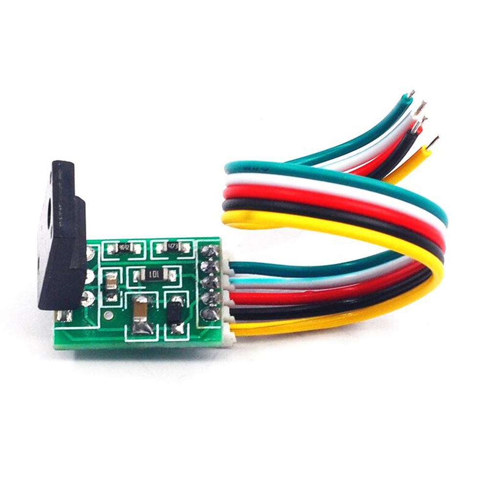
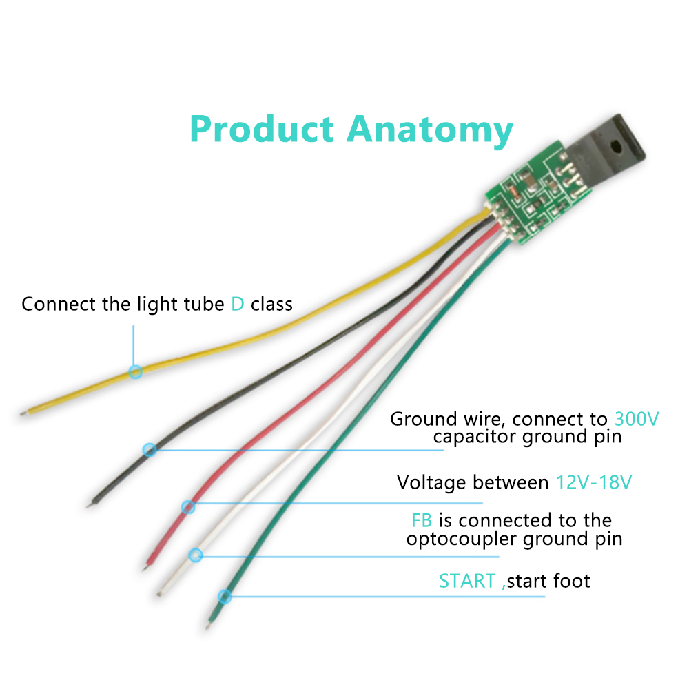
Pin Definition:
Pin 1: DRAIN, power control terminal, connected to the D pole of the original high-power MOS power tube. Usually the middle foot of the power switch tube
2 feet: GND, module ground wire 300v, connected to the negative pole of the capacitor, it can be on the same line. Directly connect the negative pole of the large filter capacitor
Pin 3: VCC, module power supply terminal, connected to the positive pole of the capacitor after rectification at the feedback winding terminal, continuous power supply, the voltage is between 12-18V.
Pin 4: FB, voltage regulator feedback, connect to pin 4 of the optocoupler, please confirm that pin 3 of the optocoupler is connected to the hot ground. If it is not the hot ground, short the optocoupler to the hot ground, and disconnect the peripheral circuit of pin 4.
5 feet: start start foot, connect the positive pole of +300v capacitor
Please be sure to take a good look at the specific connection method before modifying it, and do not blindly connect it indiscriminately. If you don't understand it, please check the circuit diagram below several times!
How to use:
1. Remove the power chip (usually 8 pins) on the original board, and the switch tube (mos tube)
2. Check the 300v capacitor and whether there is any bulge on the appearance of the capacitor at the load end. If there is any problem, replace it first.
3. Check whether there is a short circuit at the load end, AD board, high voltage board, etc.
4. Connect the corresponding circuit of the module, and carefully check that there is no wrong connection, if the wrong connection will cause the module to burst
5. Install in the original radiator position, pay attention to insulation, do not short-circuit
6. Power on, measure whether the voltage is output, if there is no output, check the reason
Precautions:
1. Before using this module, please check whether there is a short circuit at the cold end. If there is a short circuit, repair it first. If the capacitor is bulged, please replace it first. If the high-voltage package circuit is short-circuited, disconnect it first. Before this module is installed, remove it. The power chip and mos tube of the original module, at this time, the voltage of the electrode in the middle of the original switch tube to the hot ground should have a voltage of about 300v.
2. If the 3-pin of the optocoupler is not connected to the hot ground, please connect the 3-pin to the hot-ground, and at the same time remove the peripheral circuit of the 4-pin, and connect the white wire to the 4-pin position.
Troubleshooting:
1. No output: the wiring is wrong, it cannot be wrongly connected or missed, this will only burn the chip, make sure there is no short circuit at the load end, is there any problem with the optocoupler
2. The control of the optocoupler part is wrong. The 1st pin of the optocoupler is not grounded, and the 2nd pin is connected to the vcc part through a resistor.
3. The heat is serious. If the tube is used for less than 10 minutes, except for the cause of the heavy load, check the diode and capacitor on the hot-end transformer for damage.
4. The voltage is unstable and jumps: the load is too light or too heavy, the continuous jump of the voltage means that the load is too light, and the hiccup is too heavy. Generally, there may be slight voltage jumps when the load is not connected, mainly due to the different design of the transformer. , you can try to connect the load, or connect a 100 ohm resistor at the 5v end to test
Package list:
Module* 1
Module* 1
- We accept PayPal only. But we only Accept your Ebay Address,Please Make sure it's 100% right.
- Payment must be received in 5 business days of auction closing.
- Please leave note for your special request (e.g. Colors or Size) in PayPal when you pay the order.
- Any special request cannot be accepted after 24 hours of payment, because most of orders will be processed instantly and same day dispatched.
- All package need to wait 30 days(US only need 7-10 days),Please take care it.Less than 30 days,we can't take a refund.
- If the item is defect when you receive it or you are not satisfied with it, please return it within 14 days for a replacement or money back. But the items must be back in factory condition. Please contact us and double check the return address before you return it.
- If is item is defective in 12 months, you can return it to us. We will send you a new replacement after receiving the defective item.