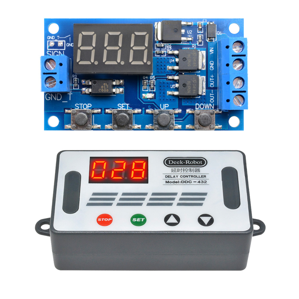

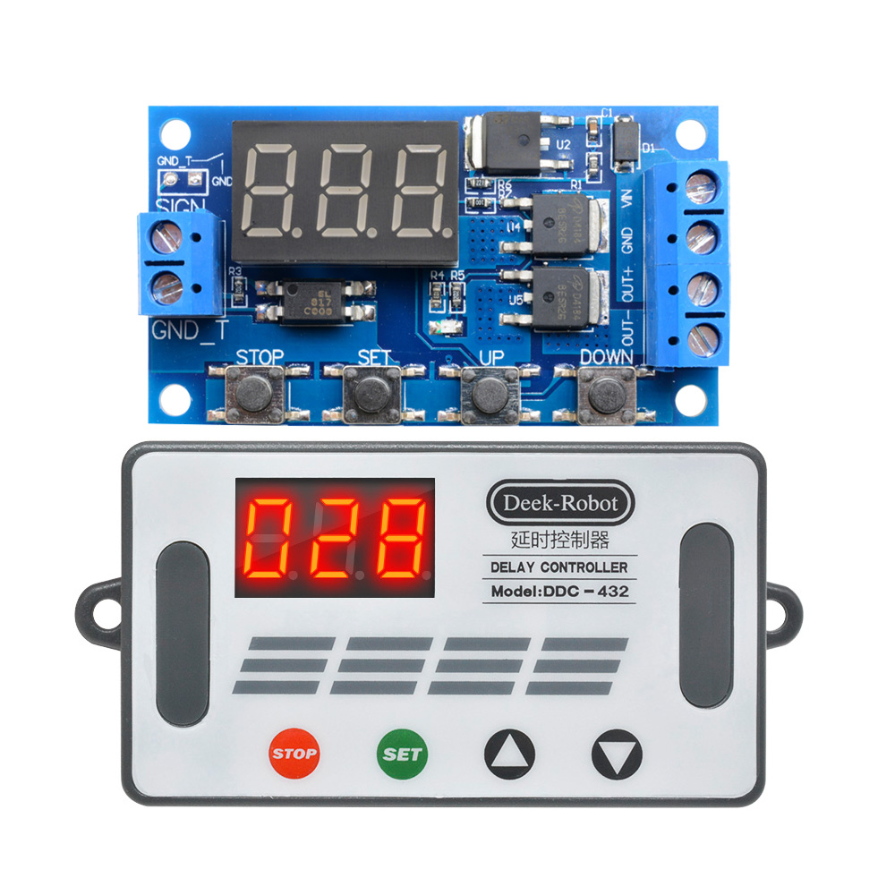
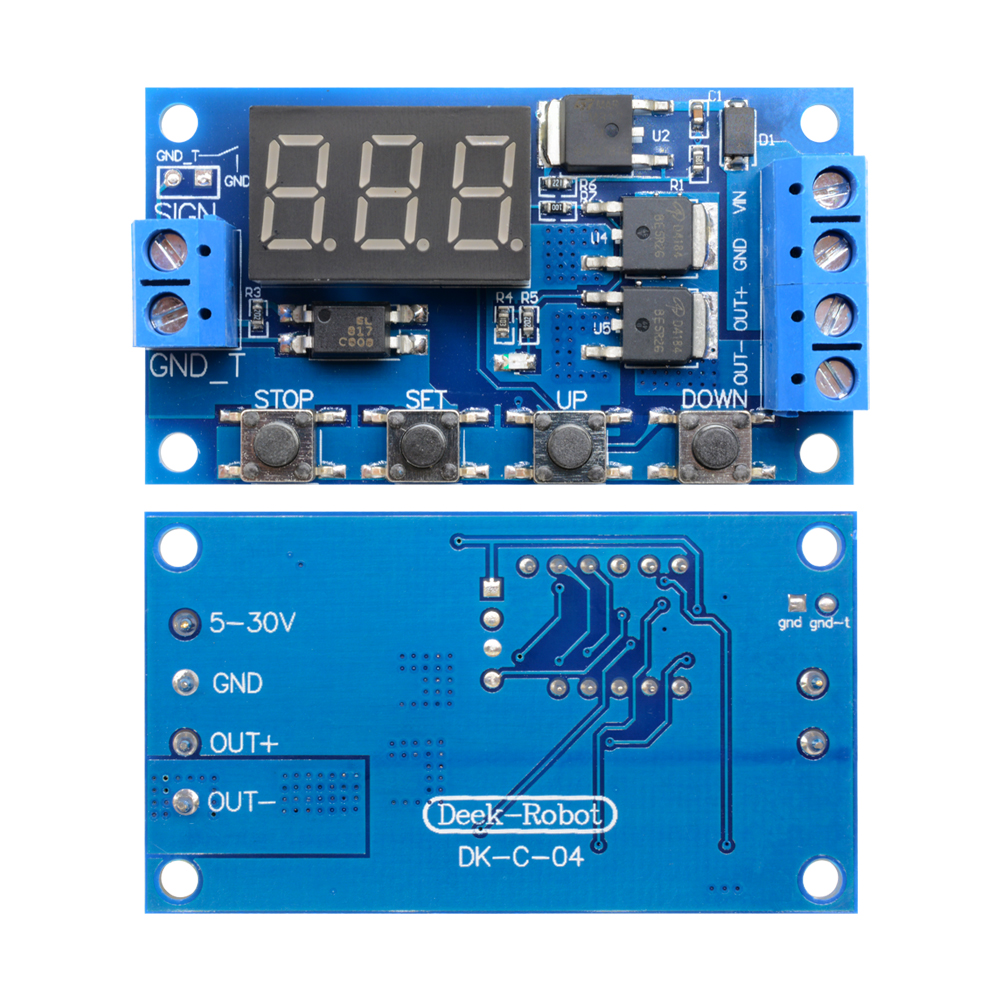
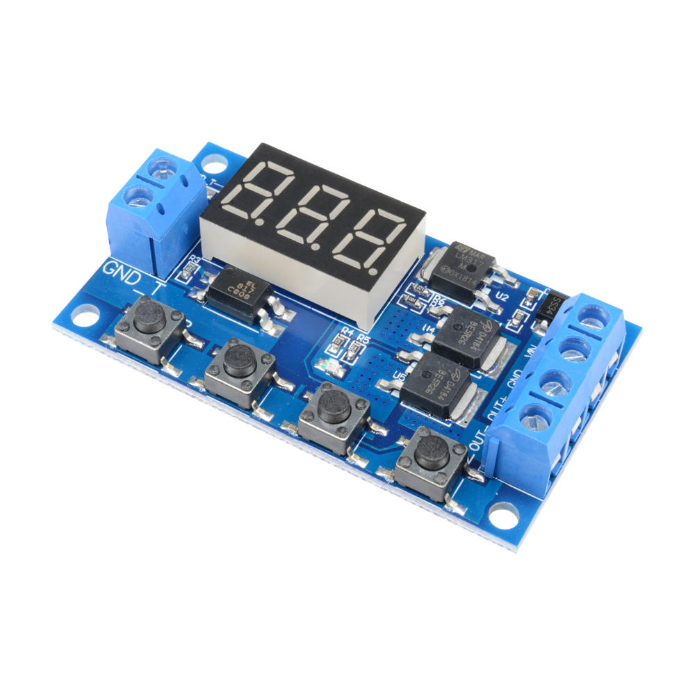
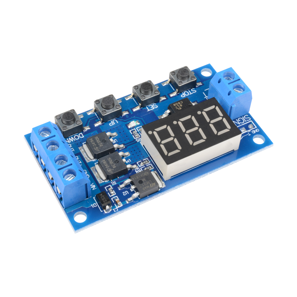
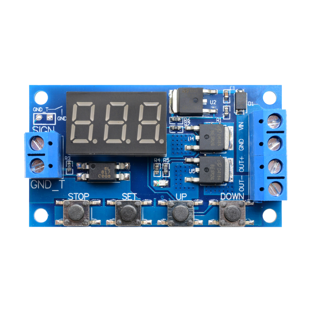
12V 24V MOS Delay Control Board
0.1 seconds (min) to 999 minutes (max) continuously adjustable.
This product is easy to use, many functions, but all buyers need to carefully read the instructions, very useful product.
Module characteristics and uses:
To achieve fast turn-on and off the circuit, an unlimited number of switching;
Conducting and cutting process does not produce noise, no spark, no electromagnetic interference;
Compared with electromagnetic relay products, longer life;
The dual-MOS parallel drive, lower resistance, more current, strong power; at room temperature, operating current of up to 15A, power up to 400W, to meet the most use of the equipment;
A method for controlling the motor, lights, LED, DC motors, micro-pumps, solenoid valves, etc., very convenient.
Highlights:
Wide voltage input (5 ~ 36V), most devices can be used, very convenient;
The interface is clear and simple, powerful, easy to understand, meet almost all your needs;
The emergency stop function (“STOP” key);With reverse polarity protection, reverse polarity will not burn the product.
Increase the sleep mode, if this mode is enabled, without any operation within 5 minutes, then automatically turn off the monitor, any key wake-up;
You can set a different OP, CL, LOP parameters, which are independent of each other, and are automatically saved;
After the module is powered down, all parameter settings are not lost.
Operating mode:
P1: trigger signal, the relay is on "OP" time, and then disconnect; in the "OP" time, as follows:
P1.1: signal is triggered again, invalid
P1.2: signal is triggered again, the clock is reset
P1.3: Signal trigger again, relay off, stop the clock;
P-2: trigger signal, the relay off "CL" of time, the relay on "OP" time, and then disconnect relay;
P3.1: trigger signal, the relay is turned on after the "OP" time, the relay off "CL" time, then the operation cycle, if the trigger signal period, the relay off, stop the clock; the number of cycles ( "LOP ") can be set.
P3.2: without triggering signal, the relay is on "OP" time, the relay off "CL" time, and has been cycling; frequency ( "LOP") cycle can be set;
P-4: signal holding function. If there is a trigger signal timing is cleared, the relay remains on; when the signal disappears, after the timing "OP" time, the relay is; if another signal during timing, timing is cleared;
Product parameters:
1: Operating voltage: 5--36V.
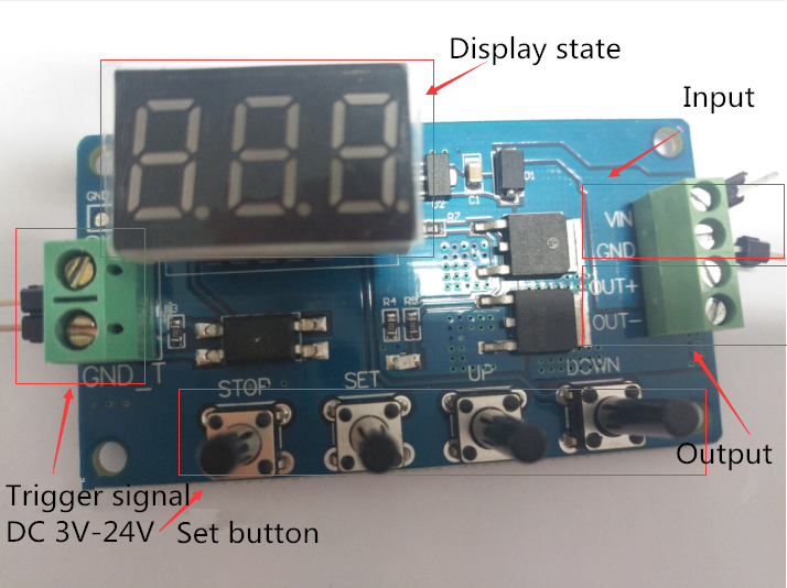
2: Trigger Source: Active-high (3.0V-24V), have optocoupler isolation, can improve the system's anti-jamming capability (customers can also shorting common ground).
3: Output capacity: DC 5V - 36V, at room temperature, continuous current 15A, power 400W! Enhance heat dissipation conditions, the maximum current up to 30A.
4: Quiescent Current: 20mA; Operating Current: 50mA
5: Life: any switching times; Working temperature: -40-85 ℃; Size: 6.0*3.4*1.2cm.
6: With optocoupler isolation, enhanced anti-jamming capability, industrial grade board.
Pay attention:
The module is an active output, the output voltage equal to the input voltage.
2.'DC + 'and' load + 'This is an internal short circuit of the poles, but' DC- 'and' load - 'poles during use can not be shorted, otherwise the load can not be controlled on and off, which is equivalent load is been carrying electricity.
Timing range
0.1 seconds (min) to 999 minutes (max) continuously adjustable
How to choose the time range?
After setting the mode selection screen parameter value by a short press "STOP" button to select the time range;
XXX. decimal point in the unit place, time range: 1 second to 999 seconds.
X decimal point in decade place, Timing range: 0.1 seconds to 99.9 seconds
X. X. decimal full brightness, Timing range: 1 minute to 999 minutes.
For example, you want to set "OP" is 3.2 seconds, then move the decimal point to decade place, the digital display 03.2
Parameter description: "OP" - conduction time, "CL" - off time, "LOP" - the number of cycles (1-999 times, "---" represents infinite loop).
These parameters are independent of each other, but is shared by each mode. For example, in P1.1 mode, set the on-time "OP" is 5 seconds, if you switch to P1.2 mode, it's "OP" will be 5 seconds too.
In the main interface (display 000), short press "SET" button will display "OP" ( "CL", "LOP") and the corresponding time XXX;
Some parameters only mode "OP" (such as the mode P1.1, P1.2, P1.3), short press the "SET" key to display only the “OP” and the corresponding time;
Some models have parameters "OP", "CL", "LOP" (such as the mode P3.1, P3.2), short press "SET" button will display "OP" and the corresponding time, “CL” and the corresponding time, “LOP” and the corresponding number of times;
In the main interface by short press "SET" key to see information about the parameters of the current mode, very convenient!
How to set parameters?
First, read the instructions to determine the required operating mode.
The module is powered up, the display at the current work mode (P1.1 default mode), then enter the main interface; press "SET" button for 2 seconds after release to enter mode selection interface; a short time by pressing "UP", "DOWN" key to select the mode (P1.1 ~ P-4).
Select the mode (such as P3.2), short press the "SET" button, then the parameter to be set flashes ( "OP" on-time, "CL" off time, "LOP" cycles ( "---" represents infinite loop)), by "UP", "DOWN" keys to adjust the parameter value, support long press (rapid increase or decrease) and short press (increase or decrease one unit); then short press the "STOP" key to select the decimal point position, select the time range (0.1 seconds to 999 minutes); short press the "sET" button to set the next parameters of the current mode of procedure is as above.
After the parameters are set, long press "SET" button for 2 seconds then release, the name of the current mode will flash once, and then return to the main screen, set the parameters of success!
The main interface: In the relay does not work status display "000" (no decimal point), with a decimal point under relay state.
Mode selection screen: Long press the "SET" key to enter, after setting is completed, long press the "SET" key to exit back to the main screen.
"STOP" button extensions:
Relays enable mode:
ON: Relay allows conduction in the "OP" on-time;
OFF: relay prohibit conduction is always closed;
In the main interface, short press the "STOP" button to switch between ON and OFF, the current in which the state will flash, and then return to the main screen. (This feature is an emergency stop function, click off the relay)
Sleep mode:
"C-P" Sleep mode: five minutes without any operation, the digital display automatically turns off, the program running as usual;
"O-d" normal mode: digital display always open;
Press the "STOP" button for two seconds and then release to switch "C-P" and "O-d" state, in which the current state of flashes and then return to the main screen.
Package Included:
1 x Trigger Cycle Timer Delay Switch 12V 24V Circuit Board MOS Tube Control Module
This product is easy to use, many functions, but all buyers need to carefully read the instructions, very useful product.
Module characteristics and uses:
To achieve fast turn-on and off the circuit, an unlimited number of switching;
Conducting and cutting process does not produce noise, no spark, no electromagnetic interference;
Compared with electromagnetic relay products, longer life;
The dual-MOS parallel drive, lower resistance, more current, strong power; at room temperature, operating current of up to 15A, power up to 400W, to meet the most use of the equipment;
A method for controlling the motor, lights, LED, DC motors, micro-pumps, solenoid valves, etc., very convenient.
Highlights:
Wide voltage input (5 ~ 36V), most devices can be used, very convenient;
The interface is clear and simple, powerful, easy to understand, meet almost all your needs;
The emergency stop function (“STOP” key);With reverse polarity protection, reverse polarity will not burn the product.
Increase the sleep mode, if this mode is enabled, without any operation within 5 minutes, then automatically turn off the monitor, any key wake-up;
You can set a different OP, CL, LOP parameters, which are independent of each other, and are automatically saved;
After the module is powered down, all parameter settings are not lost.
Operating mode:
P1: trigger signal, the relay is on "OP" time, and then disconnect; in the "OP" time, as follows:
P1.1: signal is triggered again, invalid
P1.2: signal is triggered again, the clock is reset
P1.3: Signal trigger again, relay off, stop the clock;
P-2: trigger signal, the relay off "CL" of time, the relay on "OP" time, and then disconnect relay;
P3.1: trigger signal, the relay is turned on after the "OP" time, the relay off "CL" time, then the operation cycle, if the trigger signal period, the relay off, stop the clock; the number of cycles ( "LOP ") can be set.
P3.2: without triggering signal, the relay is on "OP" time, the relay off "CL" time, and has been cycling; frequency ( "LOP") cycle can be set;
P-4: signal holding function. If there is a trigger signal timing is cleared, the relay remains on; when the signal disappears, after the timing "OP" time, the relay is; if another signal during timing, timing is cleared;
Product parameters:
1: Operating voltage: 5--36V.
2: Trigger Source: Active-high (3.0V-24V), have optocoupler isolation, can improve the system's anti-jamming capability (customers can also shorting common ground).
3: Output capacity: DC 5V - 36V, at room temperature, continuous current 15A, power 400W! Enhance heat dissipation conditions, the maximum current up to 30A.
4: Quiescent Current: 20mA; Operating Current: 50mA
5: Life: any switching times; Working temperature: -40-85 ℃; Size: 6.0*3.4*1.2cm.
6: With optocoupler isolation, enhanced anti-jamming capability, industrial grade board.
Pay attention:
The module is an active output, the output voltage equal to the input voltage.
2.'DC + 'and' load + 'This is an internal short circuit of the poles, but' DC- 'and' load - 'poles during use can not be shorted, otherwise the load can not be controlled on and off, which is equivalent load is been carrying electricity.
Timing range
0.1 seconds (min) to 999 minutes (max) continuously adjustable
How to choose the time range?
After setting the mode selection screen parameter value by a short press "STOP" button to select the time range;
XXX. decimal point in the unit place, time range: 1 second to 999 seconds.
X decimal point in decade place, Timing range: 0.1 seconds to 99.9 seconds
X. X. decimal full brightness, Timing range: 1 minute to 999 minutes.
For example, you want to set "OP" is 3.2 seconds, then move the decimal point to decade place, the digital display 03.2
Parameter description: "OP" - conduction time, "CL" - off time, "LOP" - the number of cycles (1-999 times, "---" represents infinite loop).
These parameters are independent of each other, but is shared by each mode. For example, in P1.1 mode, set the on-time "OP" is 5 seconds, if you switch to P1.2 mode, it's "OP" will be 5 seconds too.
In the main interface (display 000), short press "SET" button will display "OP" ( "CL", "LOP") and the corresponding time XXX;
Some parameters only mode "OP" (such as the mode P1.1, P1.2, P1.3), short press the "SET" key to display only the “OP” and the corresponding time;
Some models have parameters "OP", "CL", "LOP" (such as the mode P3.1, P3.2), short press "SET" button will display "OP" and the corresponding time, “CL” and the corresponding time, “LOP” and the corresponding number of times;
In the main interface by short press "SET" key to see information about the parameters of the current mode, very convenient!
How to set parameters?
First, read the instructions to determine the required operating mode.
The module is powered up, the display at the current work mode (P1.1 default mode), then enter the main interface; press "SET" button for 2 seconds after release to enter mode selection interface; a short time by pressing "UP", "DOWN" key to select the mode (P1.1 ~ P-4).
Select the mode (such as P3.2), short press the "SET" button, then the parameter to be set flashes ( "OP" on-time, "CL" off time, "LOP" cycles ( "---" represents infinite loop)), by "UP", "DOWN" keys to adjust the parameter value, support long press (rapid increase or decrease) and short press (increase or decrease one unit); then short press the "STOP" key to select the decimal point position, select the time range (0.1 seconds to 999 minutes); short press the "sET" button to set the next parameters of the current mode of procedure is as above.
After the parameters are set, long press "SET" button for 2 seconds then release, the name of the current mode will flash once, and then return to the main screen, set the parameters of success!
The main interface: In the relay does not work status display "000" (no decimal point), with a decimal point under relay state.
Mode selection screen: Long press the "SET" key to enter, after setting is completed, long press the "SET" key to exit back to the main screen.
"STOP" button extensions:
Relays enable mode:
ON: Relay allows conduction in the "OP" on-time;
OFF: relay prohibit conduction is always closed;
In the main interface, short press the "STOP" button to switch between ON and OFF, the current in which the state will flash, and then return to the main screen. (This feature is an emergency stop function, click off the relay)
Sleep mode:
"C-P" Sleep mode: five minutes without any operation, the digital display automatically turns off, the program running as usual;
"O-d" normal mode: digital display always open;
Press the "STOP" button for two seconds and then release to switch "C-P" and "O-d" state, in which the current state of flashes and then return to the main screen.
Package Included:
1 x Trigger Cycle Timer Delay Switch 12V 24V Circuit Board MOS Tube Control Module
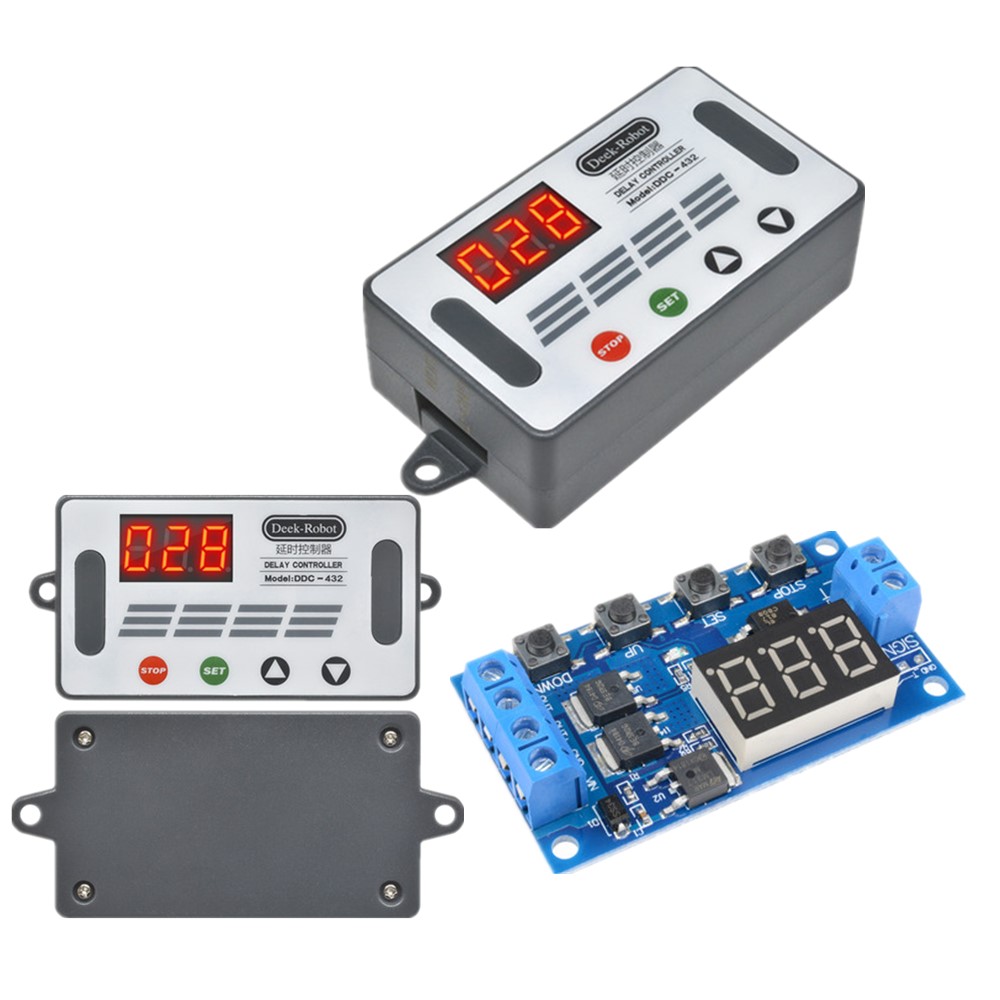
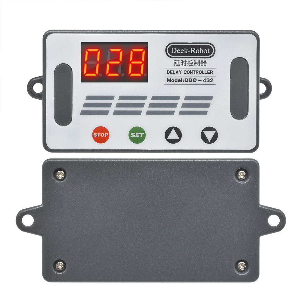
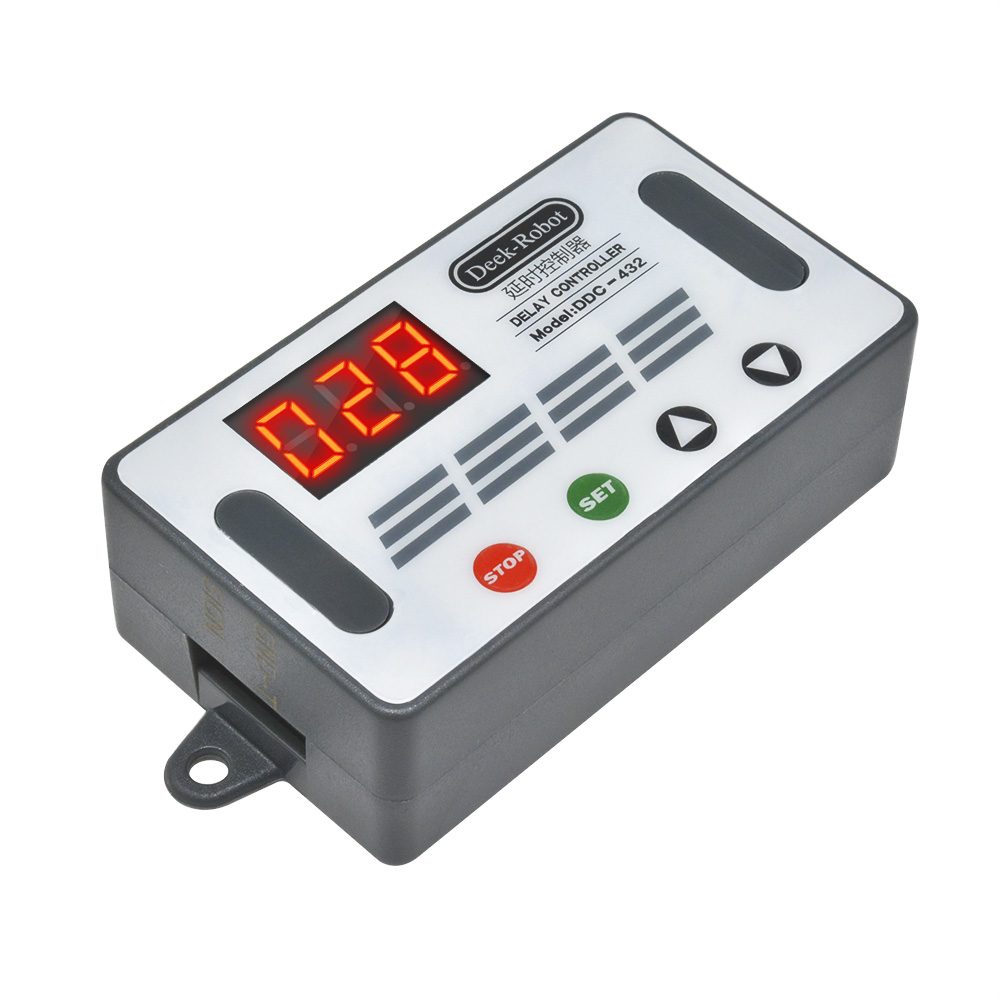
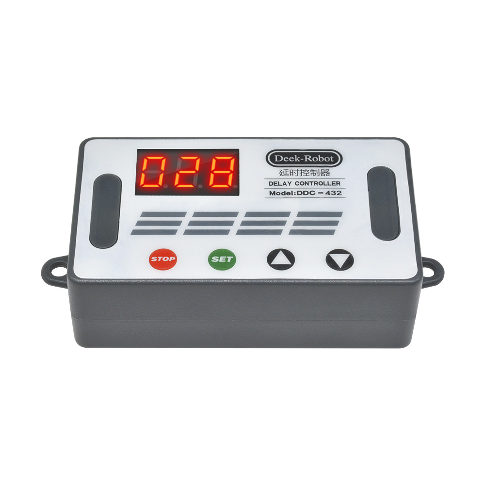
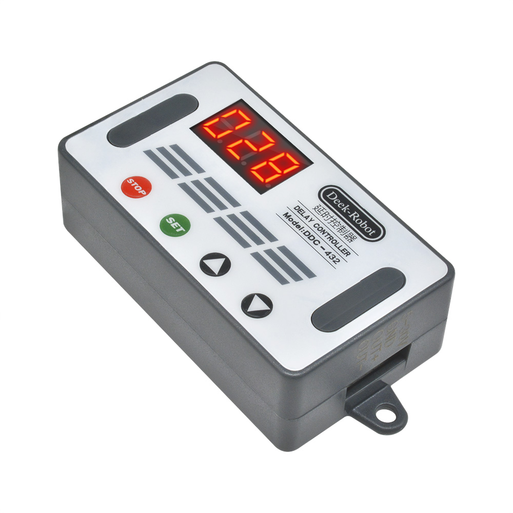
Delay Control Board with Case (DDC-432)
Description:
Dual MOS parallel active output, lower internal resistance, larger current, strong power interface, clear and simple, powerful, one-button emergency stop function (STOP button), with reverse connection protection, reverse connection, no burning, power-off memory. Increase Sleep mode, after enabling, no operation within 5 minutes, automatically turn off the display, wake up any button! You can set different OP, CL, LOP parameters, these parameters are independent of each other, save the setting parameters automatically power-down save and other functions, Almost all the needs!
Dual MOS parallel active output, lower internal resistance, larger current, strong power interface, clear and simple, powerful, one-button emergency stop function (STOP button), with reverse connection protection, reverse connection, no burning, power-off memory. Increase Sleep mode, after enabling, no operation within 5 minutes, automatically turn off the display, wake up any button! You can set different OP, CL, LOP parameters, these parameters are independent of each other, save the setting parameters automatically power-down save and other functions, Almost all the needs!
1.Product manual
Working voltage: DC5V-DC30V (wide voltage anti-connection protection)
Trigger signal source: high-level trigger DC 3.0V—24V signal ground and system ground to improve the system's anti-interference ability can also short-circuit the ground
Output capacity: DC DC 5V--36V, continuous current 15A at normal temperature, power 400W! Under the condition of auxiliary heat dissipation, the maximum current can reach 30A
Product size: 64mm*35mm*19.3mm
Mounting hole: diameter 3mm
Working temperature: -40 ° C ~ 85 ° C
2.Operating mode
P1 mode: After the signal is triggered, the MOS transistor turns on the OP time and then turns off; in the OP time, the following operation
P1.1: The signal is triggered again.
P1.2: Signal triggers re-timed again
P1.3: The signal triggers reset again, the MOS tube is disconnected, and the timing is stopped.
P-2: Give the trigger signal, after the MOS transistor is disconnected from the CL time, the MOS transistor turns on the OP time. After the timing is completed, the MOS transistor is disconnected.
P3.1: Give the trigger signal, after the MOS transistor turns on the OP time, the MOS tube turns off the CL time, then loops the above action, the signal is given again in the loop, the MOS tube is disconnected, the timing is stopped; the number of cycles (LOP) can be set.
P3.2: No need to trigger signal after power-on, MOS tube turns on OP time, MOS tube disconnects CL time, loops the above action; loop number (LOP) can be set
P-4: Signal hold function If there is a trigger signal, the timing is cleared, the MOS transistor remains on; when the signal disappears, the MOS transistor is disconnected after timing the OP; during the timing, there is a signal and the timing is cleared.
3.Relay enable mode
ON : MOS tube is allowed to conduct during OP conduction time
OFF : MOS tube is disabled, always off
Short press the STOP button on the main interface to switch between ON and OFF. The current state will flash, then return to the main interface. This function is the emergency stop function. One button is used to open and close the MOS tube.
4.Sleep mode (long press the stop button to view the current mode)
C-P sleep mode: within five minutes, without any operation, the digital tube automatically turns off the display, the program runs normally.
O-d normal mode: the digital tube is always on display
Press and hold the STOP button for 2 seconds and then release to switch the C-P and O-d states. The current state will flash and then return to the main interface.
5.Timing range
How to choose the timing range
1).After setting the parameter value in the mode selection interface, press the STOP button to select the timing range.
XXX. Decimal point is in one place, timing range: 1 second to 999 seconds
XX.X decimal point in ten, timing range: 0.1 seconds to 99.9 seconds
X.X.X. The decimal point is fully illuminated, the timing range is from 1 minute to 999 minutes.
2).For example, if you want to set the OP to 3.2 seconds, move the decimal point to ten digits, and the digital tube displays 03.2.
Parameter description: OP on time, CL off time, LOP cycle number 1-999 times, "---" stands for infinite loop.
These parameters are independent of each other, but each mode shares these parameters. For example, when the on-time OP is set to 5 seconds in P1.1, the user wants to switch to the P1.2 mode, then when entering the P1.2 setting corresponding parameters, the OP also It will be 5 seconds.
Displaying 000 on the main interface and pressing the SET button will display OPL, LOP and corresponding time XXX
If only OP in the mode, such as mode P1.1, P1.2, P1.3 time, then short press SET button will only display OP and corresponding time.
If the mode has OP, CL, LOP such as mode P3.1, P3.2 short press SET button will display OP and corresponding time, CL and corresponding time, LOP and corresponding times.
After setting the mode, it is very convenient to easily check the parameters set in the current mode by pressing the SET button on the main interface.
6.How to set parameters
1) First determine the working mode of the MOS tube
According to the working mode of the MOS tube, in the main interface (when the module is powered on, it will flash the current working mode (default P1.1 mode), then enter the main interface "press and hold the SET button for 2 seconds and then release" to enter the mode. Select the interface, press the UP, DOWN button to select the mode to be set P1.1~P-4
2) After selecting the mode to be set (for example, P3.2), press the SET button to set the corresponding parameter. At this time, the parameter to be set will flash OP ON time, CL OFF time, LOP cycle number “---” Represents an infinite loop, adjusts the parameter value through UP and DOWN, supports long press (rapid increase or decrease) and short press (increase or decrease 1 unit); after setting the parameter value, select the decimal point position by short pressing the STOP button. , select the timing range (corresponding time 0.1 seconds ~ 999 minutes); short press the SET button to set the next parameter of the current mode, the process is the same as above.
3) After setting the parameters of the selected mode, press and hold the SET button for 2 seconds to release, the currently set mode will flash, then return to the main interface and set the parameters successfully.
4) Main interface: “000” (no decimal point) is displayed when the MOS tube is not working, and the MOS tube has a decimal point in the working state.
5) Mode selection interface: long press SET button to enter, after setting is completed, long press SET button to exit, return to the main interface
Note:
The module is an active live output, and the voltage at the output (load) is equal to the input voltage DC
The module is an active live output, and the voltage at the output (load) is equal to the input voltage DC
7.Product illustration:
8.Package Included:
1*DDC-432 DC5-30V 4 button 3-digit digital tube Dual MOS Delay control board +Case