Getting Started
This section provides a brief introduction of ESP-Prog on how to do the initial hardware setup.
Description of Components
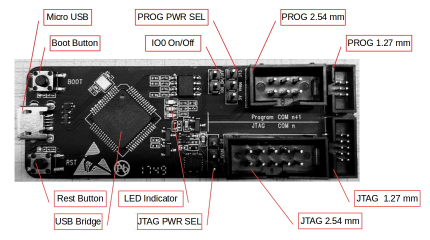
ESP-Prog - front
The key components of the board are described in a clockwise direction.
| Key Component |
Description |
|---|---|
| Micro USB |
Interface between PC and ESP-Prog. |
| Boot Button |
Download button. Holding down boot and then pressing reset initiates Firmware Download mode for downloading firmware through the serial port. |
| IO0 On/Off |
Pin Header to set the state of GPIO0 strapping pin. |
| PROG PWR SEL |
Pin Header to select power input for the Program interface. |
| PROG 2.54 mm |
Program interface with 2.54 mm (0.1”) pin pitch. |
| PROG 1.27 mm |
Program interface with 1.27 mm (0.05”) pin pitch. |
| JTAG 1.27 mm |
JTAG interface with 1.27 mm (0.05”) pin pitch. |
| JTAG 2.54 mm |
JTAG interface with 2.54 mm (0.1”) pin pitch. |
| JTAG PWR SEL |
Pin Header to select power input for the JTAG interface. |
| LED Indicator |
LED to indicate ESP-Prog state. There are three LED modes: red, green, and blue. The red LED lights up when the system is connected to the 3.3 V power. The green LED lights up when ESP-Prog is downloading data. The blue LED lights up when ESP-Prog is receiving data. |
| USB Bridge |
Single USB-to-UART bridge chip provides up to 3 Mbps of transfer rate. |
| Reset Button |
Press this button to restart the system. |
Start Application Development
Before powering up your board, please make sure that it is in good condition with no obvious signs of damage.
Required Hardware
-
ESP-Prog
-
USB 2.0 cable (Standard-A to Micro-B)
-
Computer running Windows, Linux, or macOS
-
Dupont lines or flat cables provided by Espressif for connecting the development board to ESP-Prog
Note
Be sure to use an appropriate USB cable. Some cables are for charging only and do not provide the needed data lines nor work for programming the boards.
Hardware Setup
-
Connect the ESP-Prog board and the PC USB port via a USB cable.
-
The PC then detects the two ports of ESP-Prog, indicating that the board is connected successfully. If the ports are not detected install the FT2232HL chip driver on your PC.
-
Select the output power voltage for the Program/JTAG interfaces, using PROG PWR SEL/JTAG PWR SEL pin headers.
-
Connect the ESP-Prog and ESP user board with the flat cables provided by Espressif.
-
Start programming (downloading) or JTAG debugging, using the official software tools or scripts provided by Espressif.
Package includes:
1 x ESP-Prog Development Board
2 x cables
Two flexible flat cables:
One cable to connect to 2*5-PIN 2.54 mm male shrouded box header.
One cable to connect to 2*3-PIN 127 mm male shrouded box header.
Hardware Reference
Block Diagram
The block diagram below shows the components of ESP-Prog and their interconnections.
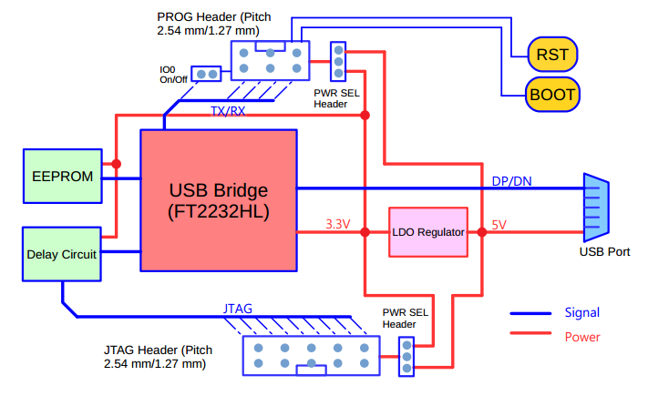
ESP-Prog Block Diagram (click to enlarge)
Power Supply Options
There are three mutually exclusive ways to provide power to the board:
-
ESP-Prog USB Port, default power supply (recommended)
-
5 V and G (GND) pins
-
3.3 V and G (GND) pins
Header Block
The two tables below provide the Name and Function of the pins on both sides of the board (Program Interface and JTAG Interface). The pin names are shown in the front view of the ESP-Prog board. The numbering is the same as in the ESP-Prog Schematic (PDF).
Program Interface
| No. |
Name |
Function |
|---|---|---|
| 1 |
ESP_EN |
Enable signal |
| 2 |
VDD |
Power supply |
| 3 |
ESP_TXD |
TX pin |
| 4 |
GND |
Ground |
| 5 |
ESP_RXD |
RX pin |
| 6 |
ESP_IO0 |
Strapping pin |
JTAG Interface
| No. |
Name |
Function |
|---|---|---|
| 1 |
VDD |
Power supply |
| 2 |
ESP_TMS |
JTAG TMS pin, mode selection |
| 3 |
GND |
Ground |
| 4 |
ESP_TCK |
JTAG TCK pin, clock input |
| 5 |
GND |
Ground |
| 6 |
ESP_TDO |
JTAG TDO pin |
| 7 |
GND |
Ground |
| 8 |
ESP_TDI |
JTAG TDI pin |
| 9 |
GND |
Ground |
| 10 |
NC |
None |


On Nov 19, 2023 at 20:26:54 PST, seller added the following information: