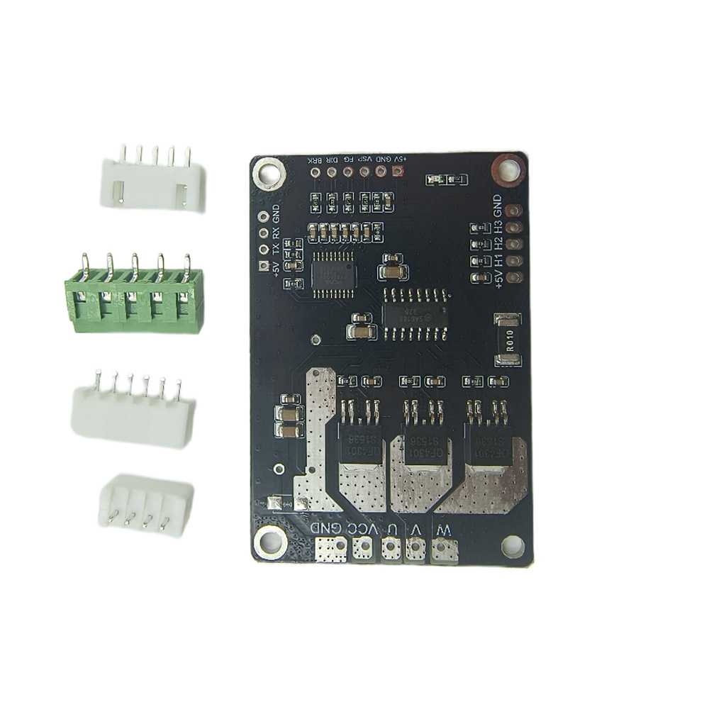
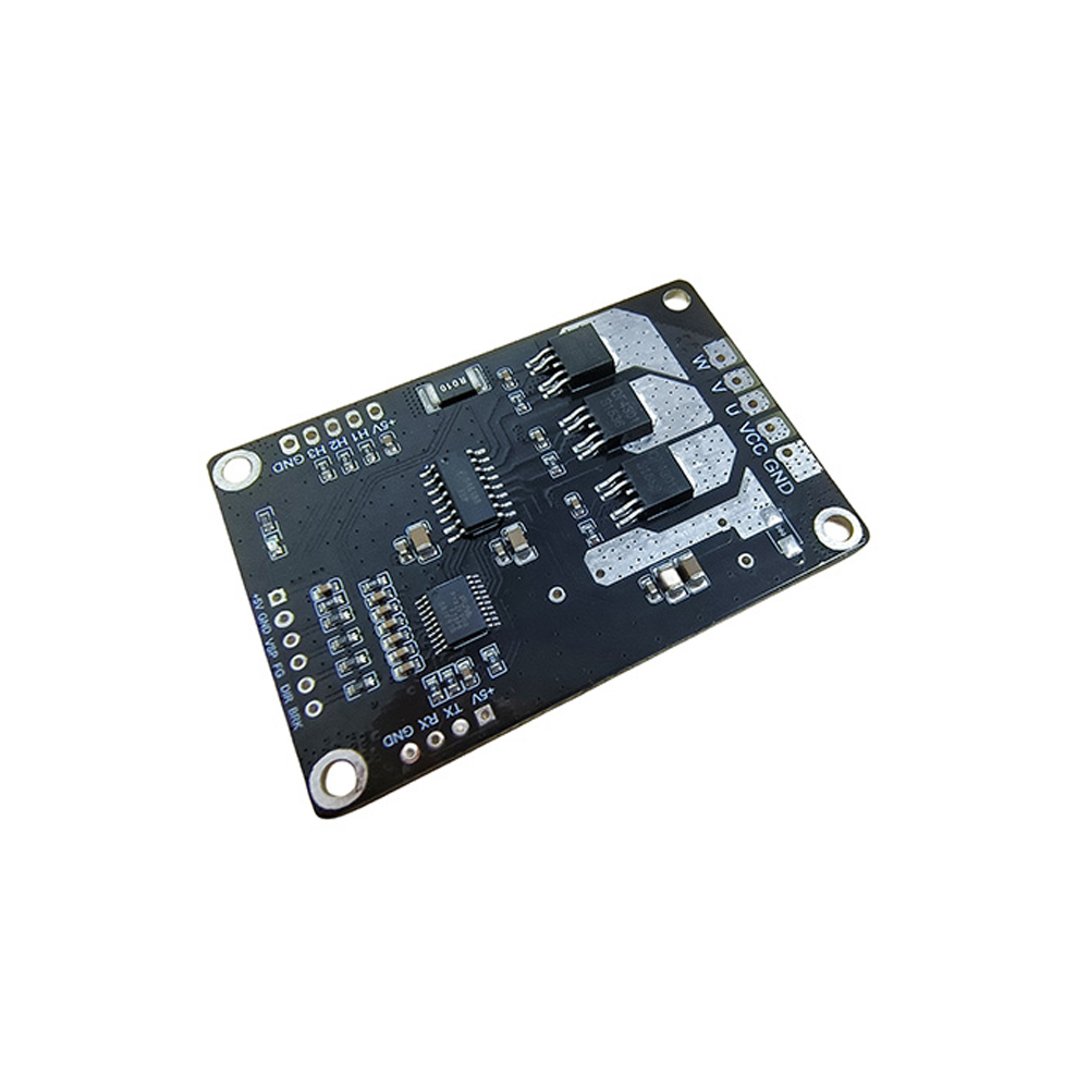
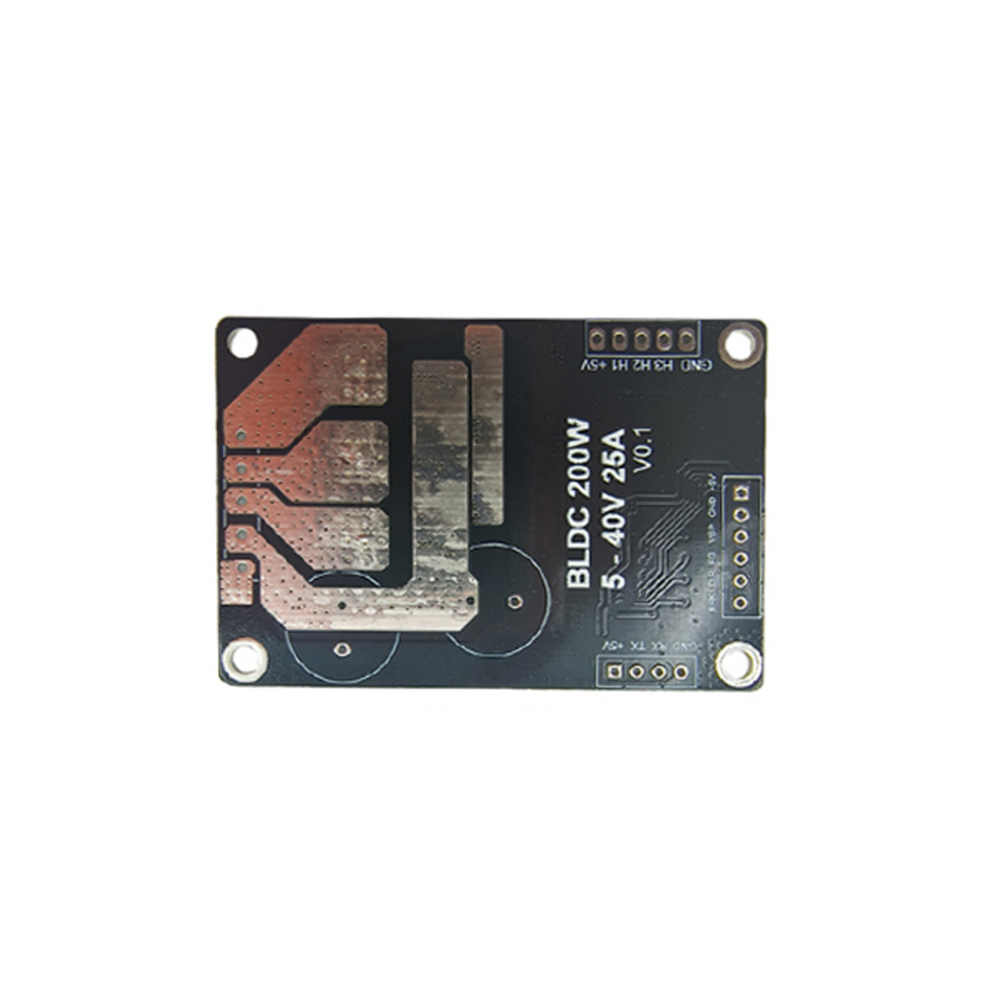
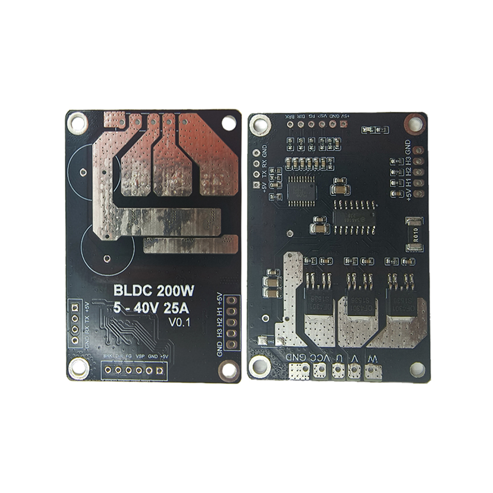
PWM Three-phase Motor Drive Module BLDC 200W 5-40V 25A DC Three-phase Brushless Motor Forward and Reverse Controller with Hall
BLDC 200W 5-40V 25A inductive brushless motor drive module, is for Hall (inductive) DC brushless three-phase motor development of a wide voltage, large current, with a simple peripheral circuit, complete functions, small size, simple debugging, high driving efficiency, flexible application, wide application and other characteristics of high performance module. Motor control can be realized only by connecting the three-phase line and Hall line of the motor.
Specification:
Operating voltage: 5V-40V
Continuous operation: 15A
Maximum current: 25A
Max power: 200W
Maximum speed: 150,000 RPM
Temperature protection: 100°C (85°C recovery)
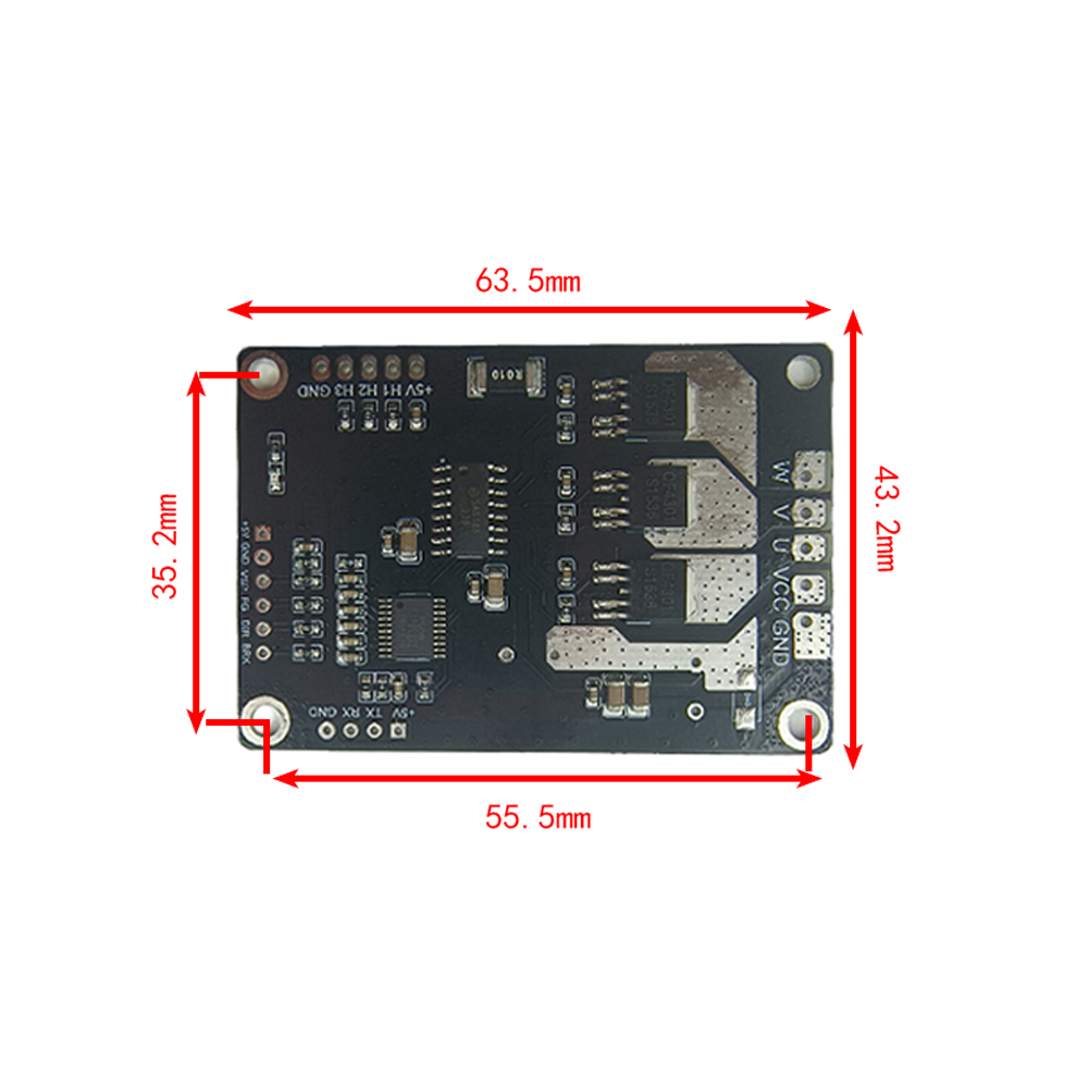
Module size: 63.5*43.2mm
Note: The drive module is bare board, and it is not necessary to force heat dissipation to drive the motor with power below 100W, as long as normal ventilation is ensured. If the drive motor power exceeds 100W, it must be forced to dissipate heat, add heat sink or fan heat dissipation, and pay attention to the insulation problem of the drive board when adding.
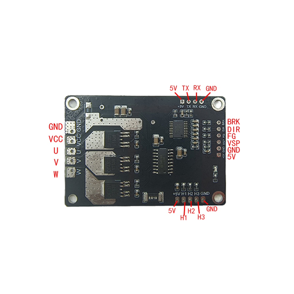
Hall sensor usage:
Before use, please confirm that the DC brushless motor is hall. Generally, the motor with Hall has 8 wires (applicable), and the motor without hall has only 3 wires.
The module can support 120 degrees or 60 degrees of Hall electrical Angle, the default is 120 degrees,
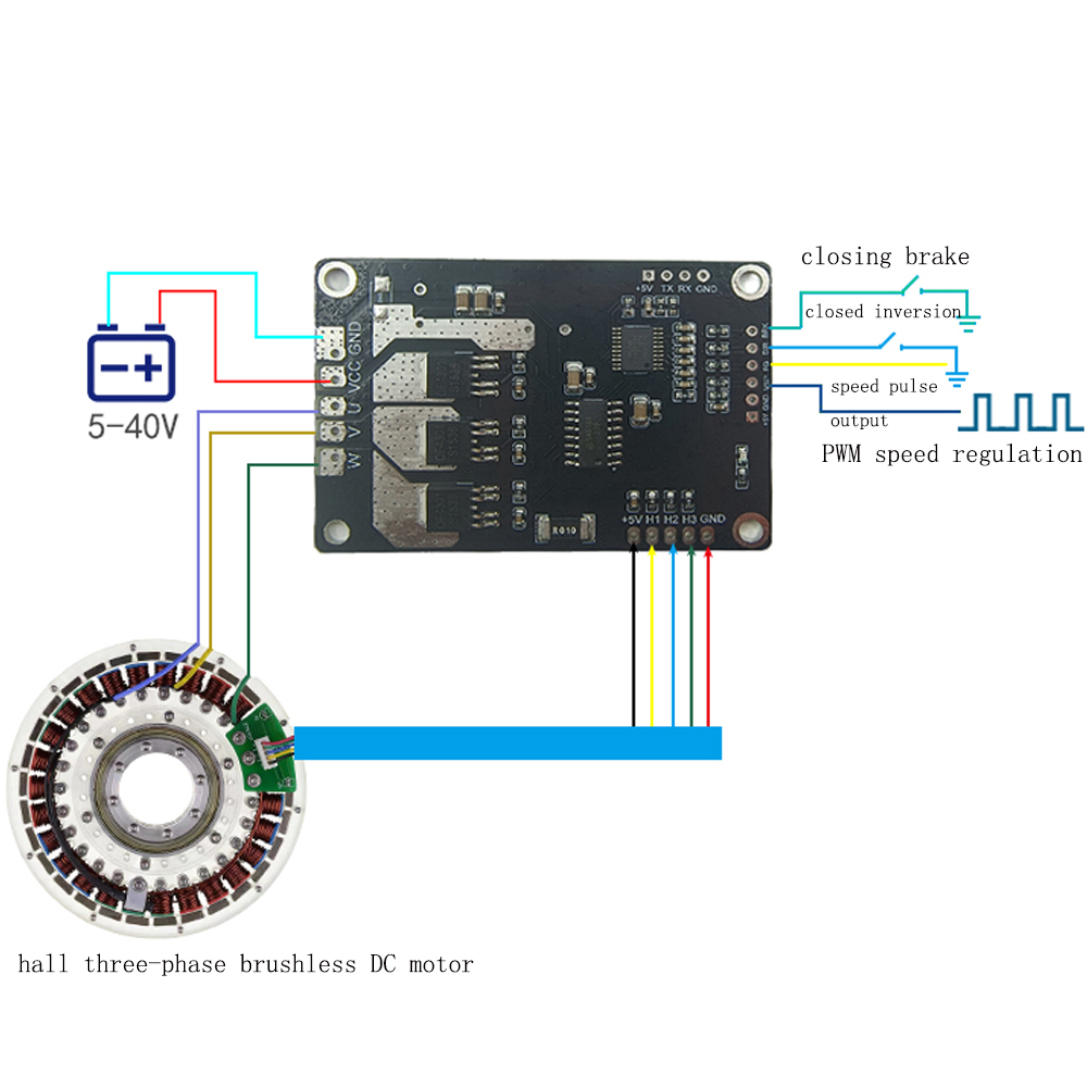
There are Hall motor, 5 hall wiring, of which 2 are Hall power cables, 3 are Hall signal cables, according to the specifications or colors provided by the motor manufacturer to distinguish, wiring can not be mistaken. Note: Distinguish between motor wire, Hall signal wire, and Hall power cord.
If you are not clear about the definition of Hall line and phase line, please try the following methods:
1. Set the power supply to low voltage to limit the output of small current;
2. Connect five Hall cables. Do not change the Hall power cables after connecting them.
3. Assume that the color of the three-phase line of the motor is: red, black and white, and connect to the U, V and W of the PCB board respectively. According to the 6 different combinations in the following table, the smooth operation or efficiency is the best proof that the wiring is correct, and only 1 of the 6 combinations is correct.
Before finding the correct relationship, do not use high voltage and high current, otherwise the module may be damaged, the relationship is not generally the following phenomena:
1. After power-on, the motor can not start normally without reaction or jitter can not rotate normally when starting;
2. It is difficult to start with slight shaking, and sometimes it is necessary to turn it artificially;
3. The motor can turn in a certain direction, and the other direction can not turn and some have slight noise;
4. The motor starts jitter and has no noise, the current is large, and the power tube is obviously hot.
Note:
1. Due to the light and screen difference, the item's color may be slightly different from the pictures.
2. Please allow 1-3cm differences due to manual measurement.
Package Included:
1x Motor Drive Module