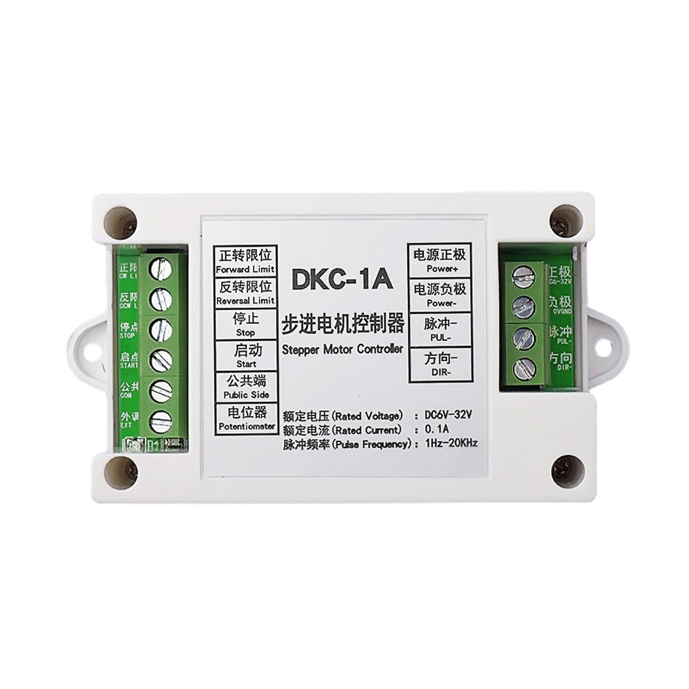
DC Industrial Stepper Motor Controller Motor Forward and Reverse Controller Servo Pulse Generator Potentiometer Governor Board
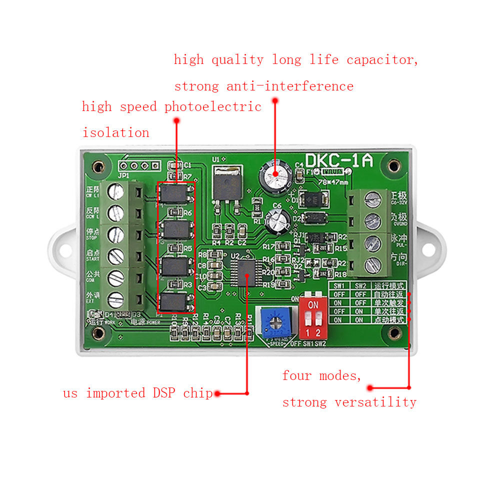
The controller uses imported original high-speed intelligent chip as the platform, and the software inherits the stability, reliability and strong anti-interference of the original DKC-1. Suitable for all kinds of harsh environment factory site. At the same time, some functions are added to make the controller more practical and convenient.
The controller is suitable for sensor controlled round-trip motion control, fixed length control, speed control and so on.
Specifications:
Ultra-wide voltage input: DC5V-32V
Multiple protection functions: reverse protection, over voltage protection, over current protection
Speed control performance: intelligent automatic switching between on-board speed control and external speed control
Acceleration and deceleration: Optimized S-type acceleration with an immediate stop function
Output frequency: up to 20KHz pulse frequency.
Input/output: All inputs are optically coupled and the output is negative pulse. The input signal is low and valid.
Function description
1. Round-trip automatic mode: After the controller in this mode is triggered to start (the public end and the enabled input end touch), the motor automatically moves back and forth between the forward and reverse limits. Stop input until triggered.
2, single trigger mode: After the mode is triggered to start, the motor will stop when it hits the positive rotation limit. If the motor is triggered again, the motor will reverse and the motor will stop when it hits the reverse limit. Trigger the start motor again and repeat the positive rotation cycle.
3, single round trip mode: After the mode triggers the start, the motor is turned, when the positive rotation limit is stopped, and then the reverse is started, when the reverse limit is stopped.
4, the point mode: the starting end and the public end are connected to turn, let go of stop; The connection between the stop end and the public end is reversed, and the release stop is performed.
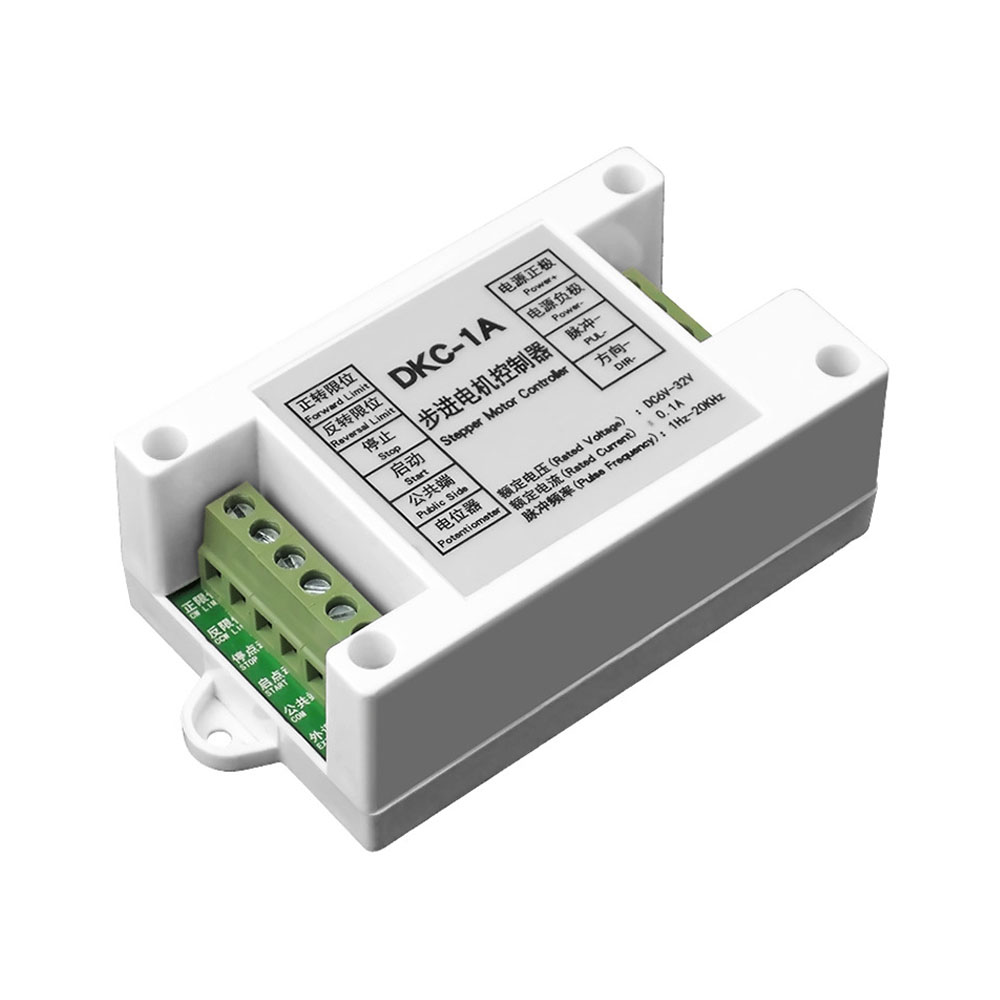
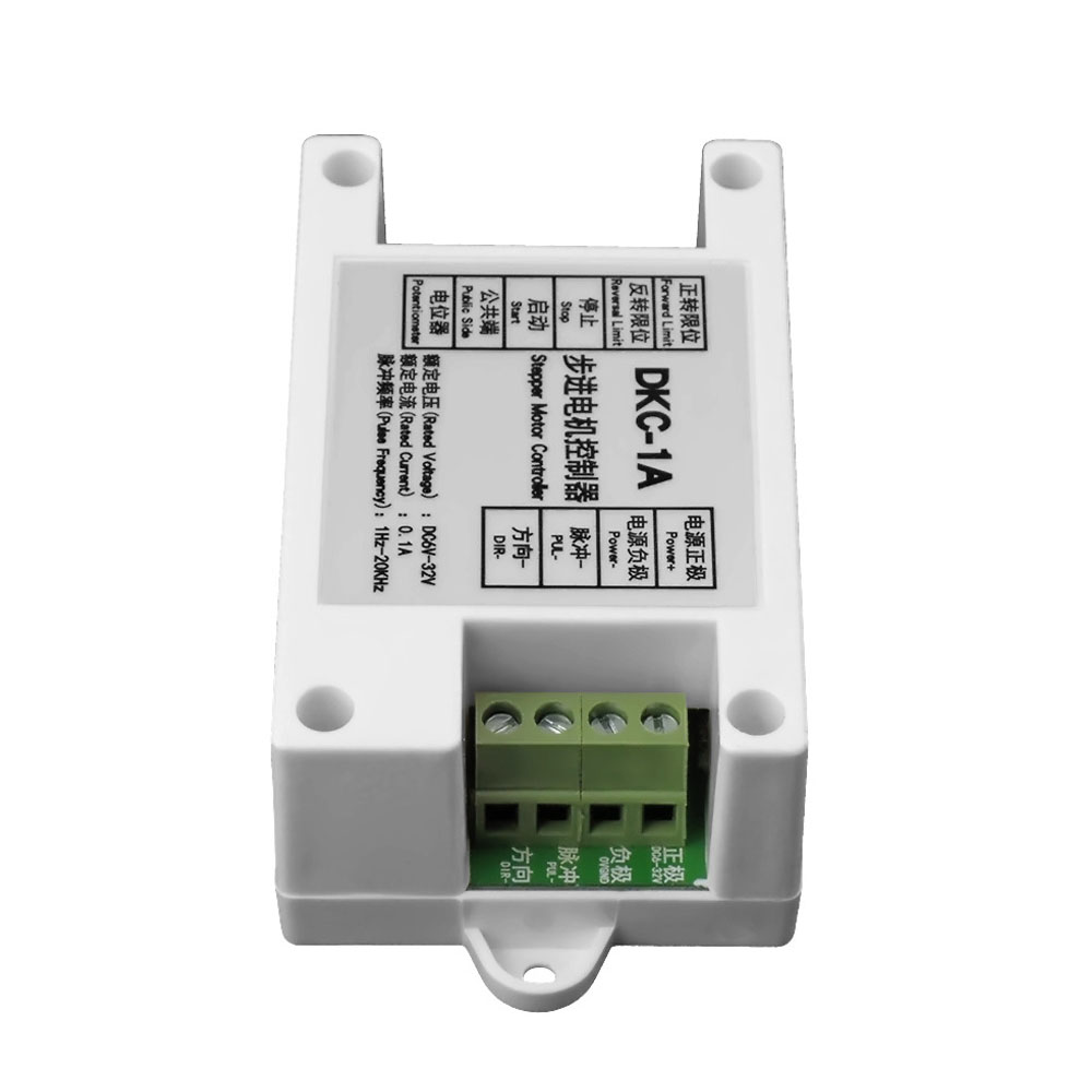
Wiring and other instructions:
1. The controller is a general stepper motor and servo motor controller. General stepper motor drivers, servo motor drivers can be matched to use, regardless of the size of the motor can be controlled.
Different motor drivers have different port markings, but the interface functions are the same.
EM=ENA=PREE Enable
PUL=PULS=CLK pulse
DIR=CW=CCW direction
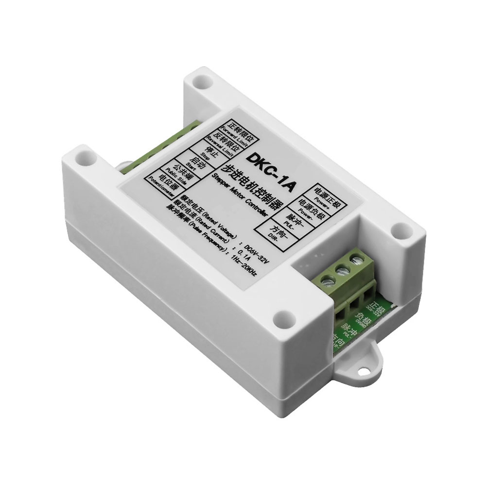
This controller uses the common positive connection method:
Drivers PUL+ and DIR+ are connected to the positive +24V power supply
Controller PUL- connected to driver pulse input (PUL-, PULS-, CLK-)
Drive DIR- Connect to drive direction input (DIR-, CW-, CWW-)
EN+, EN- This is usually empty
Note: When debugging the controller for the first time, it is required to connect the controller and the driver, the motor, and the power supply, and then connect a small piece of wire at the common end. After power-on, use the other end of the wire to start and stop the input port to simulate the role of the switch, so that after debugging each function is normal, then step by step connect each switch, external potentiometer and other accessories.
Note:
1.Due to the light and screen difference, the item's color may be slightly different from the pictures.
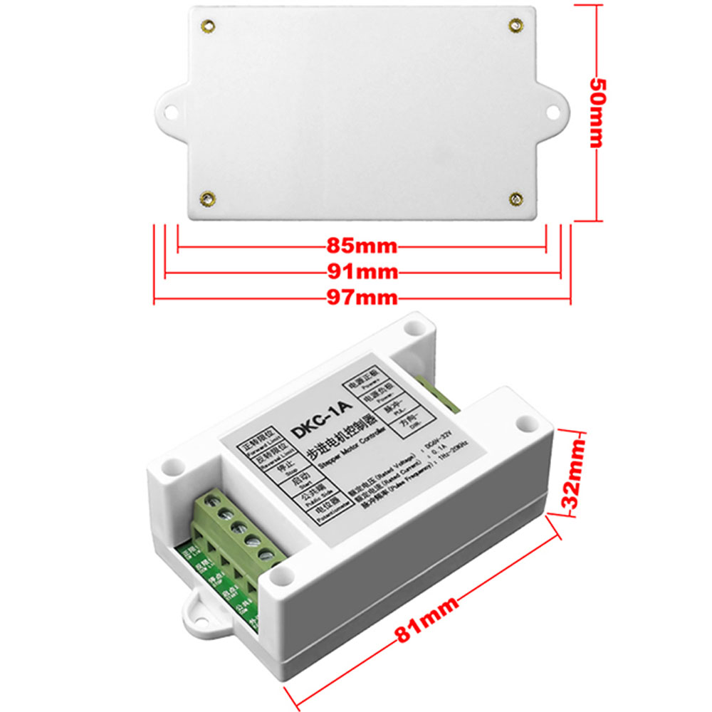
2.Please allow 1-3cm differences due to manual measurement.
Package Includes:
1x Stepper Motor Controller