Introduction:
TL494 PWM adjustment module, which can adjust the output frequency and duty cycle, is widely used in switching power supply, PWM drive circuit, etc.
Features:
The output PWM frequency can be adjusted within the range of 300Hz-100KHz, and the duty cycle can be adjusted up to 96%
The output driving ability is strong, and the signal is stable.
Parameters:
Module working voltage: DC 7V-40V limit 42V
Maximum output current: 250mA
Output voltage DC 5V
Maximum power consumption: 1000mW
Working environment temperature: 0-70 ℃

The positioning holes 1 and 2 are M2.5 and the through hole diameter is 2.7mm
As shown in the figure above, the left VCC / GND is the power input terminal VCC connected to a positive voltage of DC 7-40V, and GND is grounded. OUT / GND on the right is the PWM signal output terminal, OUT is the positive signal output terminal, and GND can be grounded.
R5 is to adjust the output duty cycle, R6 is the output frequency
Instructions:
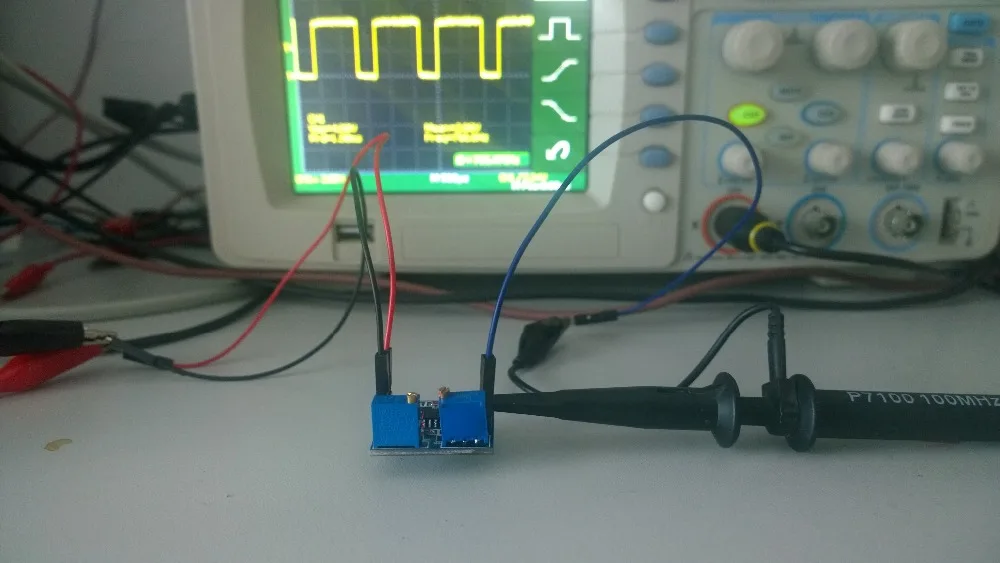
Connect VCC to DC 7V-40V, as shown

The red indicator light indicates that the module power supply is working properly.
Connect the OUT interface of this module to the positive terminal of the oscilloscope signal input terminal, and GND to the negative terminal of the oscilloscope signal input terminal.
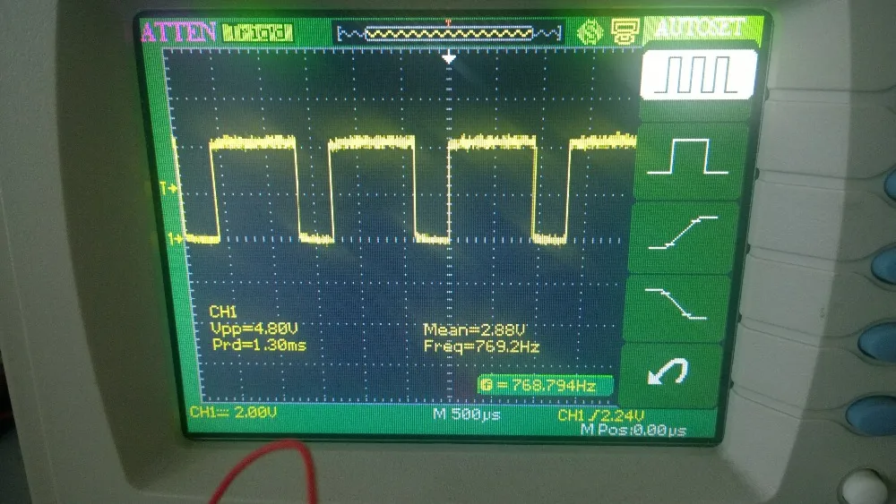
Adjust the duty cycle and frequency
Among them, adjusting the potentiometer R5 is to adjust the duty cycle, and adjusting the potentiometer R6 is to adjust the frequency.
Adjust the output frequency to more than 700 Hz, as shown below
PWM drive
After adjusting the required frequency and duty cycle, directly connect OUT to the positive input terminal of the driving circuit, and GND to the negative input terminal of the driving circuit.

