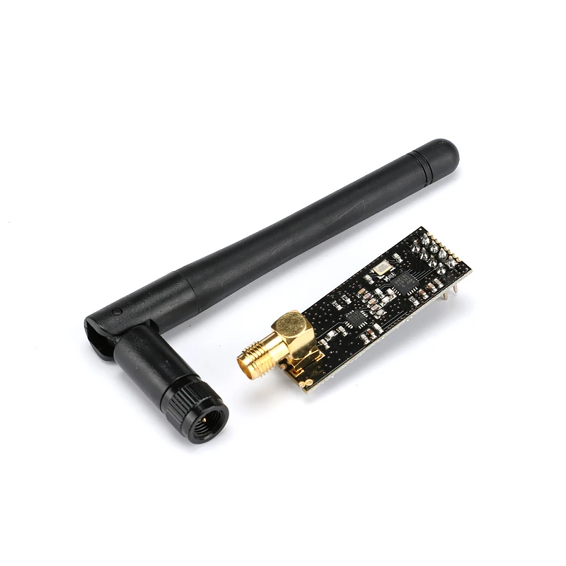
Note: 2.4G Antenna, place an order for the customers who need it, and do not select the ones who don't need it, thank you!
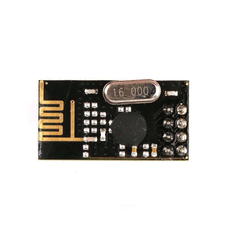
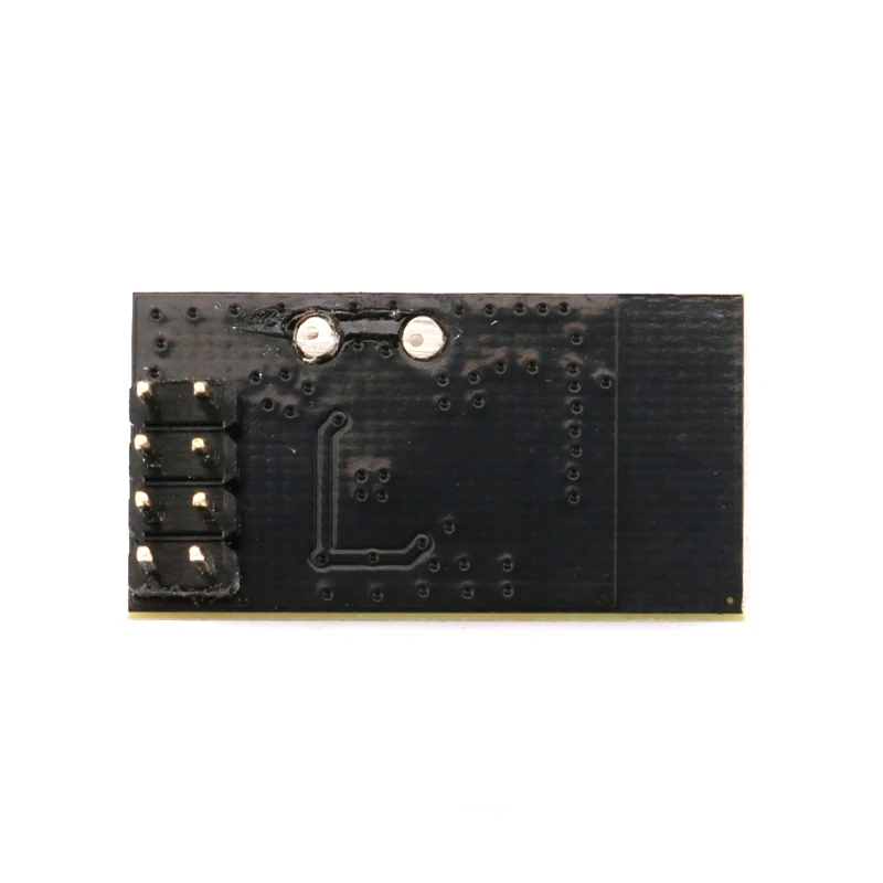
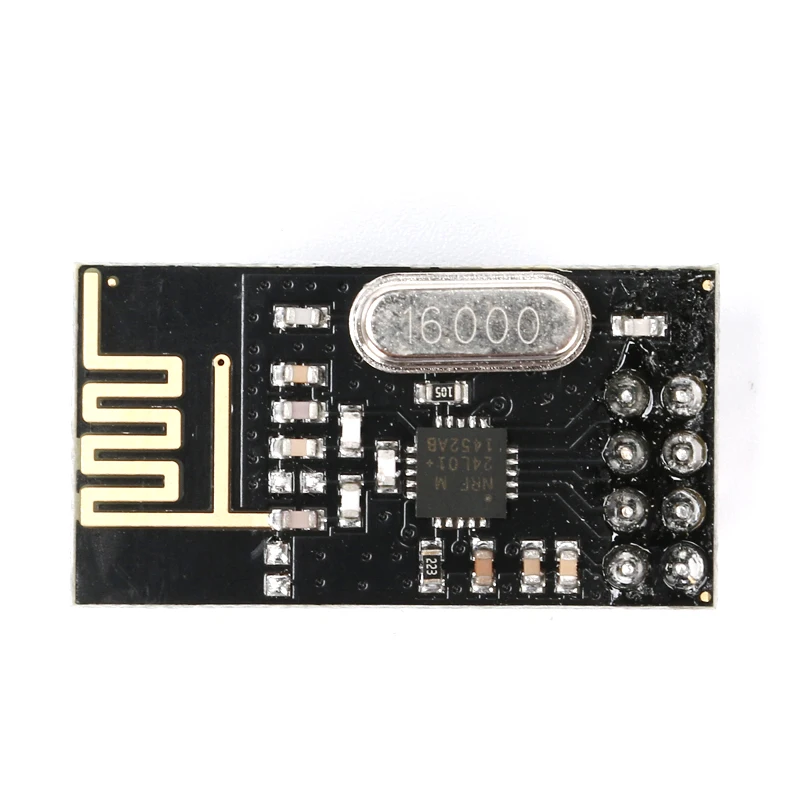
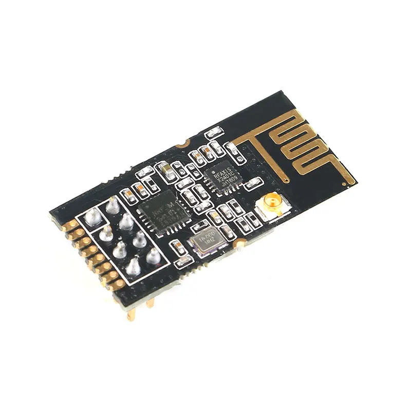
2.4G NRF24L01
Product Features:
This module uses the domestic RF bonding chip BK2425, which integrates all the high-speed signal processing parts related to the RF protocol. Since the link layer is fully integrated on the module, it is very easy to develop. Automatic detection and automatic retransmission of lost data packets, retransmission time and number of retransmissions can be controlled by software, automatically storing data packets that have not received the response signal; after receiving valid data, the module automatically sends a response signal without additional programming; Carrier detection - fixed frequency detection, built-in hardware CRC error detection and point-to-multipoint communication address control packet transmission error counter and carrier detection function can be used for frequency hopping setting, six channel receiving channel addresses can be set at the same time, and the receiving channel can be selectively opened. . The SPI interface of the BK2425 can be connected by the hardware SPI port of the MCU or simulated by the I/O port of the MCU. The internal FIFO can interface with various high and low speed microprocessors, which is convenient for using low-cost MCU.
Product parameters:
-
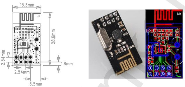
Onboard 2.4G PCB antenna, ISM band, 2.54mm pin DIP8 package, compact size, easy to use for embedded applications.
-
Support six-channel data reception (one pair of six)
-
Support GFSK modulation
-
Supports 2Mbps/1Mbps/250Kbps data rate, and can set different transmit power
-
Multi-frequency point: meet the needs of multi-point communication and frequency hopping communication, 2400MHz~2527MHz, 1MHz frequency hopping stepping
-
Internally integrated high PSRR LDO
-
Wide supply voltage range: 1.9~3.6V, typical 3.3V
-
Average emission current as low as 18mA (4dBm)
-
Receive sensitivity: -96dBm@250kbps
-
Transmit power up to 4dBm
-
4-wire SPI interface with 8MHz speed
-
Internal packet processing engine
-
Transceiver data hardware interrupt output
-
Working temperature: -20 ° C ~ 85 ° C
-
The best transmission distance: less than 120 meters (250kbp open environment without shielding without electromagnetic interference) reliable distance recommended to use within 30%-50%
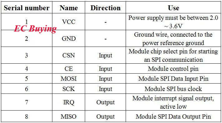
The VCC pin voltage range is between 2.0V and 3.6V. It cannot be outside this range. If it exceeds 3.6V, the module will be burned. The recommended voltage is around 3.3V. In addition to the power supply VCC and ground, the other pins can be directly connected to the normal 5V MCU IO port without level shifting. Of course, it is more suitable for the 3V microcontroller.
Note:
When connecting with the P0 port of the 51 series MCU, it is necessary to add a 10K pull-up resistor, which is not required to connect with the remaining ports. For other series of single-chip microcomputers, if it is 5V, please refer to the output current of the IO port of this series of microcontrollers. If it exceeds 10mA, it needs to be divided by series resistors, otherwise it will easily burn the module! If it is 3.3V, it can directly connect with the IO port of nRF24l01 module. Wire connection, such as AVR series MCU. The module's SPI rate can only support up to 8M, which is generally recommended at 1M or a few hundred K SPI rate.
The wireless module is a static-sensitive device. Pay attention to the static electricity protection when using it. Especially in the dry winter, try not to remove the device on the touch module to avoid unnecessary damage.
The wireless module recommends using a DC power supply with a small ripple, and the operating voltage is recommended to operate at 3.3V. The grounding of the module should be stable and reliable, and the ground wire should be as close as possible to the power supply. If you use a switching power supply, you must strengthen the retraction to avoid the ripple and spikes of the switching power supply affecting the operating characteristics of the module.
The module uses a PCB antenna. This antenna is easily affected by external circuits. When using it, please do not leave the line or place the device under and around the antenna. If possible, it is best to hollow out. The 2.4G frequency is relatively high, and various materials have certain influences. The general plastic has little effect. If there is a metal object, it will have a significant impact. In this case, it is recommended to use an SMA feeder to connect the SMA antenna.
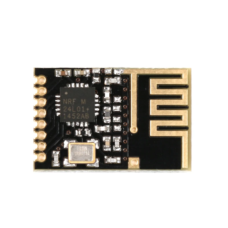
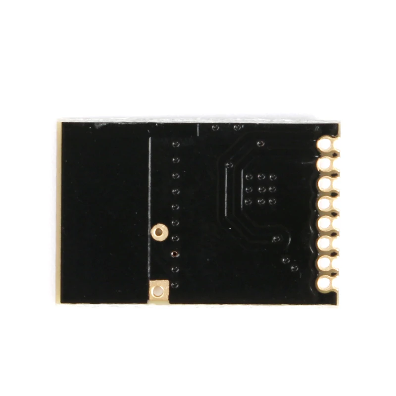
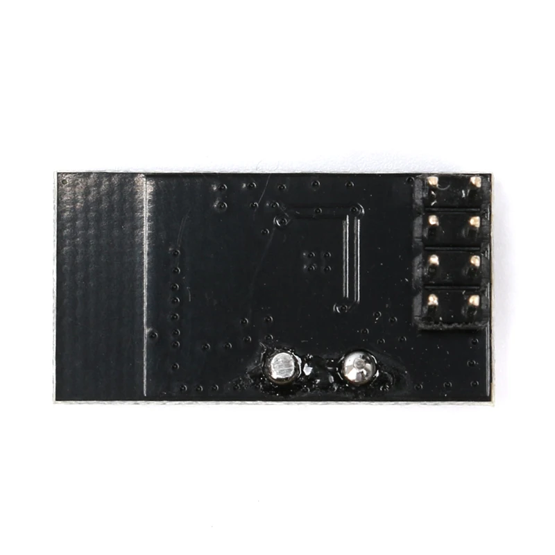
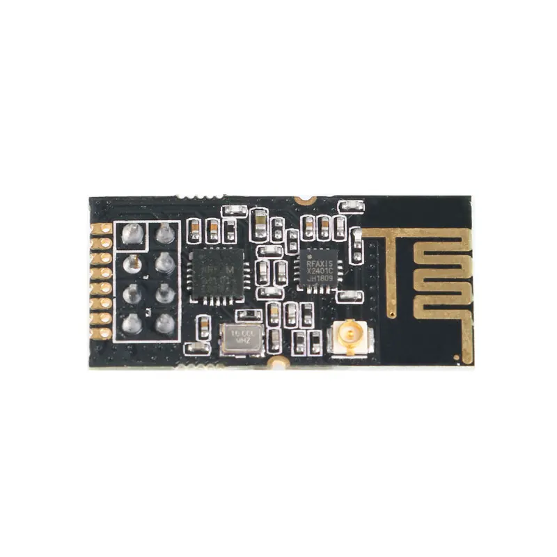
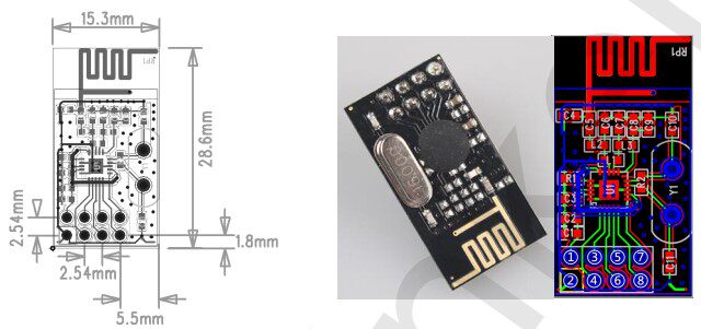
NRF24l01 Mini
Product Features:
This module uses the domestic RF bonding chip BK2425, which integrates all the high-speed signal processing parts related to the RF protocol. Since the link layer is fully integrated on the module, it is very easy to develop. Automatic detection and automatic retransmission of lost data packets, retransmission time and number of retransmissions can be controlled by software, automatically storing data packets that have not received the response signal; after receiving valid data, the module automatically sends a response signal without additional programming; Carrier detection - fixed frequency detection, built-in hardware CRC error detection and point-to-multipoint communication address control packet transmission error counter and carrier detection function can be used for frequency hopping setting, six channel receiving channel addresses can be set at the same time, and the receiving channel can be selectively opened. . The SPI interface of the BK2425 can be connected by the hardware SPI port of the MCU or simulated by the I/O port of the MCU. The internal FIFO can interface with various high and low speed microprocessors, which is convenient for using low-cost MCU.
Product parameters:
-
Onboard 2.4G PCB antenna, ISM band, 2.54mm pin DIP8 package, compact size, easy to use for embedded applications.
-
Support six-channel data reception (one pair of six)
-
Support GFSK modulation
-
Supports 2Mbps/1Mbps/250Kbps data rate, and can set different transmit power
-
Multi-frequency point: meet the needs of multi-point communication and frequency hopping communication, 2400MHz~2527MHz, 1MHz frequency hopping stepping
-
Internally integrated high PSRR LDO
-
Wide supply voltage range: 1.9~3.6V, typical 3.3V
-
Average emission current as low as 18mA (4dBm)
-
Receive sensitivity: -96dBm@250kbps
-
Transmit power up to 4dBm
-
4-wire SPI interface with 8MHz speed
-
Internal packet processing engine
-
Transceiver data hardware interrupt output
-
Working temperature: -20 ° C ~ 85 ° C
-
The best transmission distance: less than 120 meters (250kbp open environment without shielding without electromagnetic interference) reliable distance recommended to use within 30%-50%
The VCC pin voltage range is between 2.0V and 3.6V. It cannot be outside this range. If it exceeds 3.6V, the module will be burned. The recommended voltage is around 3.3V. In addition to the power supply VCC and ground, the other pins can be directly connected to the normal 5V MCU IO port without level shifting. Of course, it is more suitable for the 3V microcontroller.
Note:
When connecting with the P0 port of the 51 series MCU, it is necessary to add a 10K pull-up resistor, which is not required to connect with the remaining ports. For other series of single-chip microcomputers, if it is 5V, please refer to the output current of the IO port of this series of microcontrollers. If it exceeds 10mA, it needs to be divided by series resistors, otherwise it will easily burn the module! If it is 3.3V, it can directly connect with the IO port of nRF24l01 module. Wire connection, such as AVR series MCU. The module's SPI rate can only support up to 8M, which is generally recommended at 1M or a few hundred K SPI rate.
The wireless module is a static-sensitive device. Pay attention to the static electricity protection when using it. Especially in the dry winter, try not to remove the device on the touch module to avoid unnecessary damage.
The wireless module recommends using a DC power supply with a small ripple, and the operating voltage is recommended to operate at 3.3V. The grounding of the module should be stable and reliable, and the ground wire should be as close as possible to the power supply. If you use a switching power supply, you must strengthen the retraction to avoid the ripple and spikes of the switching power supply affecting the operating characteristics of the module.
The module uses a PCB antenna. This antenna is easily affected by external circuits. When using it, please do not leave the line or place the device under and around the antenna. If possible, it is best to hollow out. The 2.4G frequency is relatively high, and various materials have certain influences. The general plastic has little effect. If there is a metal object, it will have a significant impact. In this case, it is recommended to use an SMA feeder to connect the SMA antenna.
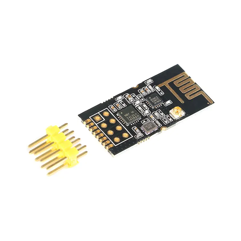
2.4G NRF24L01 SI24R1
Product Features:
This module uses the domestic RF bonding chip BK2425, which integrates all the high-speed signal processing parts related to the RF protocol. Since the link layer is fully integrated on the module, it is very easy to develop. Automatic detection and automatic retransmission of lost data packets, retransmission time and number of retransmissions can be controlled by software, automatically storing data packets that have not received the response signal; after receiving valid data, the module automatically sends a response signal without additional programming; Carrier detection - fixed frequency detection, built-in hardware CRC error detection and point-to-multipoint communication address control packet transmission error counter and carrier detection function can be used for frequency hopping setting, six channel receiving channel addresses can be set at the same time, and the receiving channel can be selectively opened. . The SPI interface of the BK2425 can be connected by the hardware SPI port of the MCU or simulated by the I/O port of the MCU. The internal FIFO can interface with various high and low speed microprocessors, which is convenient for using low-cost MCU.
Product parameters:
-
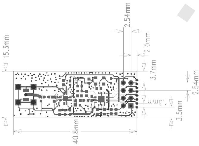
Onboard 2.4G PCB antenna, ISM band, 2.54mm pin DIP8 package, compact size, easy to use for embedded applications.
-
Support six-channel data reception (one pair of six)
-
Support GFSK modulation
-
Supports 2Mbps/1Mbps/250Kbps data rate, and can set different transmit power
-
Multi-frequency point: meet the needs of multi-point communication and frequency hopping communication, 2400MHz~2527MHz, 1MHz frequency hopping stepping
-
Internally integrated high PSRR LDO
-
Wide supply voltage range: 1.9~3.6V, typical 3.3V
-
Average emission current as low as 18mA (4dBm)
-
Receive sensitivity: -96dBm@250kbps
-
Transmit power up to 4dBm
-
4-wire SPI interface with 8MHz speed
-
Internal packet processing engine
-
Transceiver data hardware interrupt output
-
Working temperature: -20 ° C ~ 85 ° C
-
The best transmission distance: less than 120 meters (250kbp open environment without shielding without electromagnetic interference) reliable distance recommended to use within 30%-50%
The VCC pin voltage range is between 2.0V and 3.6V. It cannot be outside this range. If it exceeds 3.6V, the module will be burned. The recommended voltage is around 3.3V. In addition to the power supply VCC and ground, the other pins can be directly connected to the normal 5V MCU IO port without level shifting. Of course, it is more suitable for the 3V microcontroller.
Note:
When connecting with the P0 port of the 51 series MCU, it is necessary to add a 10K pull-up resistor, which is not required to connect with the remaining ports. For other series of single-chip microcomputers, if it is 5V, please refer to the output current of the IO port of this series of microcontrollers. If it exceeds 10mA, it needs to be divided by series resistors, otherwise it will easily burn the module! If it is 3.3V, it can directly connect with the IO port of nRF24l01 module. Wire connection, such as AVR series MCU. The module's SPI rate can only support up to 8M, which is generally recommended at 1M or a few hundred K SPI rate.
The wireless module is a static-sensitive device. Pay attention to the static electricity protection when using it. Especially in the dry winter, try not to remove the device on the touch module to avoid unnecessary damage.
The wireless module recommends using a DC power supply with a small ripple, and the operating voltage is recommended to operate at 3.3V. The grounding of the module should be stable and reliable, and the ground wire should be as close as possible to the power supply. If you use a switching power supply, you must strengthen the retraction to avoid the ripple and spikes of the switching power supply affecting the operating characteristics of the module.
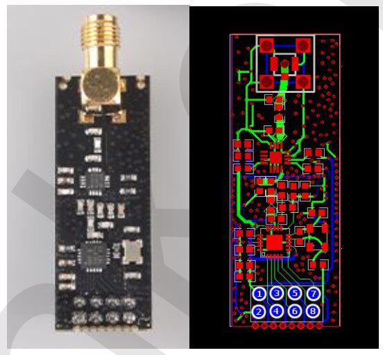
The module uses a PCB antenna. This antenna is easily affected by external circuits. When using it, please do not leave the line or place the device under and around the antenna. If possible, it is best to hollow out. The 2.4G frequency is relatively high, and various materials have certain influences. The general plastic has little effect. If there is a metal object, it will have a significant impact. In this case, it is recommended to use an SMA feeder to connect the SMA antenna.
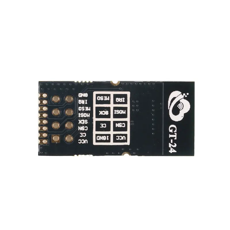
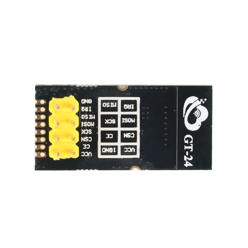
NRF24L01 GT-24 SMD+NRF24L01 GT-24 Direct Insert
Product introduction:
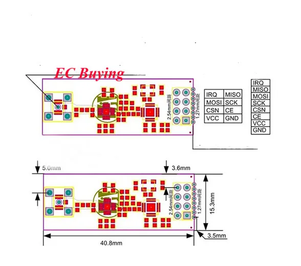
The GT-24 module is a 2. HGHz, 100mW, high speed (up to 2Mbps airspeed), high stability, industrial-grade wireless transceiver. Volume number module. The module comes with a high-performance PCB antenna, accurate impedance matching, and nRF21L.0IP radio frequency chip, which has higher reliability, more power grade, and longer transmission distance and lower power than nRF24L01. In addition, the YRFX2 101 power amplifier chip, built-in LNA, improves the receiving sensitivity by 10dBm. It works in the ISU band of 2. 4GHz 2. 5Gz. The module has sufficient transmitting power, good frequency harmonic characteristics, small harmonics, small channel crosstalk, and ultra-small volume. It is a model of Murata original material and industrial standard. And it has a standard spacing of 2.54mm in-line interface and 1.27am patch interface, which is convenient for users to freely use various circuits. In addition, the GT-24 module also comes with a built-in PCB antenna and an external antenna for the ipx carrier, which greatly exerts the free characteristics of the module and gives the sub-user the maximum free experience.
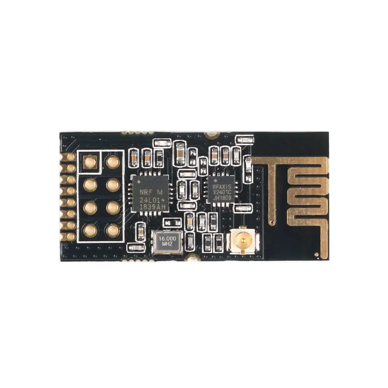
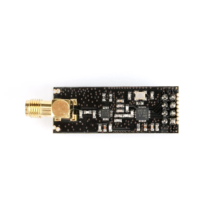
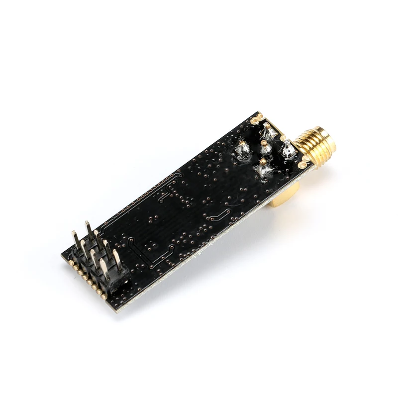
NRF24L01 Antenna
Product Features:
This module uses the domestic RF bonding chip BK2425, which integrates all the high-speed signal processing parts related to the RF protocol. Since the link layer is fully integrated on the module, it is very easy to develop. Automatic detection and automatic retransmission of lost data packets, retransmission time and number of retransmissions can be controlled by software, automatically storing data packets that have not received the response signal; after receiving valid data, the module automatically sends a response signal without additional programming; Carrier detection - fixed frequency detection, built-in hardware CRC error detection and point-to-multipoint communication address control packet transmission error counter and carrier detection function can be used for frequency hopping setting, six channel receiving channel addresses can be set at the same time, and the receiving channel can be selectively opened. . The SPI interface of the BK2425 can be connected by the hardware SPI port of the MCU or simulated by the I/O port of the MCU. The internal FIFO can interface with various high and low speed microprocessors, which is convenient for using low-cost MCU.
Product parameters:
-
Onboard 2.4G PCB antenna, ISM band, 2.54mm pin DIP8 package, compact size, easy to use for embedded applications.
-
Support six-channel data reception (one pair of six)
-
Support GFSK modulation
-
Supports 2Mbps/1Mbps/250Kbps data rate, and can set different transmit power
-
Multi-frequency point: meet the needs of multi-point communication and frequency hopping communication, 2400MHz~2527MHz, 1MHz frequency hopping stepping
-
Internally integrated high PSRR LDO
-
Wide supply voltage range: 1.9~3.6V, typical 3.3V
-
Average emission current as low as 18mA (4dBm)
-
Receive sensitivity: -96dBm@250kbps
-
Transmit power up to 4dBm
-
4-wire SPI interface with 8MHz speed
-
Internal packet processing engine
-
Transceiver data hardware interrupt output
-
Working temperature: -20 ° C ~ 85 ° C
-
The best transmission distance: less than 120 meters (250kbp open environment without shielding without electromagnetic interference) reliable distance recommended to use within 30%-50%
The VCC pin voltage range is between 2.0V and 3.6V. It cannot be outside this range. If it exceeds 3.6V, the module will be burned. The recommended voltage is around 3.3V. In addition to the power supply VCC and ground, the other pins can be directly connected to the normal 5V MCU IO port without level shifting. Of course, it is more suitable for the 3V microcontroller.
Note:
When connecting with the P0 port of the 51 series MCU, it is necessary to add a 10K pull-up resistor, which is not required to connect with the remaining ports. For other series of single-chip microcomputers, if it is 5V, please refer to the output current of the IO port of this series of microcontrollers. If it exceeds 10mA, it needs to be divided by series resistors, otherwise it will easily burn the module! If it is 3.3V, it can directly connect with the IO port of nRF24l01 module. Wire connection, such as AVR series MCU. The module's SPI rate can only support up to 8M, which is generally recommended at 1M or a few hundred K SPI rate.
The wireless module is a static-sensitive device. Pay attention to the static electricity protection when using it. Especially in the dry winter, try not to remove the device on the touch module to avoid unnecessary damage.
The wireless module recommends using a DC power supply with a small ripple, and the operating voltage is recommended to operate at 3.3V. The grounding of the module should be stable and reliable, and the ground wire should be as close as possible to the power supply. If you use a switching power supply, you must strengthen the retraction to avoid the ripple and spikes of the switching power supply affecting the operating characteristics of the module.
The module uses a PCB antenna. This antenna is easily affected by external circuits. When using it, please do not leave the line or place the device under and around the antenna. If possible, it is best to hollow out. The 2.4G frequency is relatively high, and various materials have certain influences. The general plastic has little effect. If there is a metal object, it will have a significant impact. In this case, it is recommended to use an SMA feeder to connect the SMA antenna.