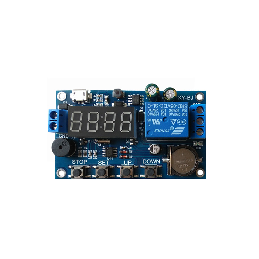
DC 5-60V Real Time Timer Delay Relay Module Switch Control Clock Synchronization Multiple Mode Control Relay with Buzzer Alarm
Specifications:
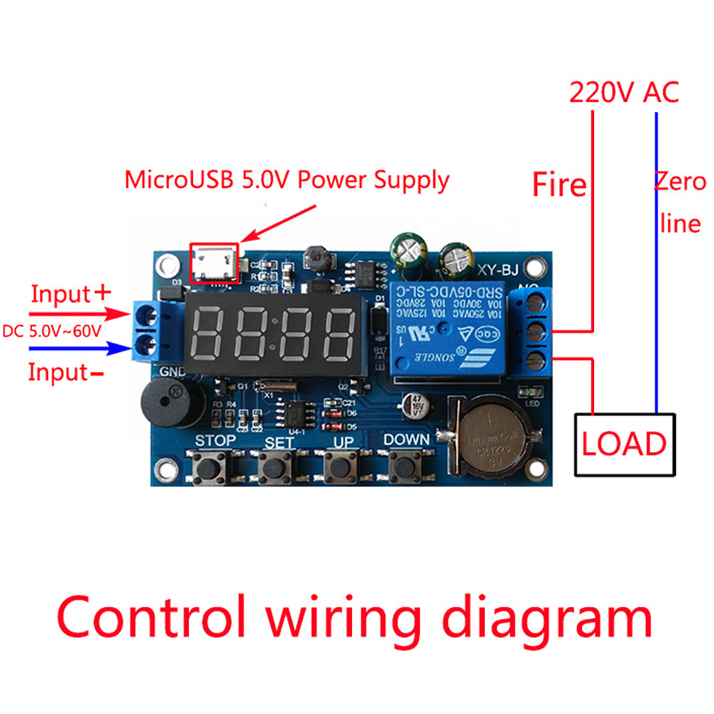
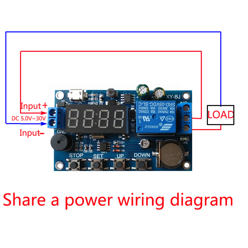
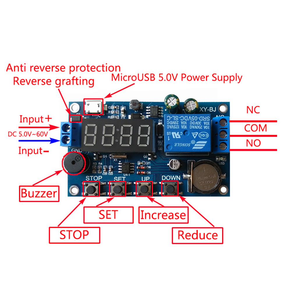
Wide voltage power supply 5.0V~60V ;
A mode can be set for multiple time periods,can reach 5 time periods; with a buzzer alarm function.
Mode Introduction:
OPE:relay closing time point , CLE:relay off time point Time period PE1-PE-5 5 time periods ( OPE to CLE is a time period) "----":function shielding.
P-1:The relay closes or outputs pulses every day to the OPE time point, and the relay turns off or outputs pulses to the CLE time point .
P-2:set the day , to the OPE time point when the relay closed or output pulse , to the CLE time point when the relay disconnect / or output pulse.
P-3:set the date of the month,to the OPE time point when the relay closed or output pulse,to the CLE time point when the relay is off or output pulse.
P-4:Set the date 1 to date 2 , start every day at the OPE time point ,end to the CLE time point , relay action or output pulse .
P-5:As with P-4,only the month can not be set.
Parameter Setting:
First , how to set the time?
In the time to run the interface , press the DOWN button for a while:
Step 1:Select the time period:PE-1~PE-5 Press UP and DOWN to select;
Step 2: Press the SET key to select the mode : P-1~P-5( Set this time period to the corresponding mode ) by pressing the UP and DOWN keys.("----"means to block this time period).
Note : Each time period can be repeated from the "----",P-1~ P-5 one of the optional ; For example , you can let five time periods at the same time work in the P-1 mode, or let Time period 1 work in P-1 mode,time period 2 work in P-2 mode and so on.
Step 3 : After the mode selection is finished , press the SET key to enter the time period setting interface , set the interface in the time period , press the SET key to switch the parameter , "OPE" start time point , "CLE"end point , "dAE" date information;
Step 4 : After setting the parameters to exit the settings ,press the SET button for 2 seconds to release , auto matically check whether the parameter settings are legal , legal to save the parameters , return to the time to run the interface ; if the parameter is wrong , "ERR"eminder ( for example , stop time or Date < = start time or date ) , return to the parameter setting interface;Additional features:Each "time period"can be set individually.
In the specific parameter setting intertace ( after the second step ) , press the STOP button to switch the output mode:
OUT1:Start time point turns on the relay , the end time is off the relay;
OUT2: Outputs 1S pulse to start or end time ;
In the specific parameter setting intertace ( after the second step ) , press the STOP button for a while to switch the ringing mode:
BLL0 : Ring disable
BLL1 : Ring enable
Note : When the bell rings , press any button to stop thering.
Extended Functions:
STOP key function expansion :
Relay enable mode:
1. ON : enable relay on;
2 .OFF : Do not turn on the relay , it is always off;
Press the STOP button on the time display interface to switch between ON and OFF,the current status will flash , and then return to the main interface . ( This function is the emergency stop function , press once to close the closed relay)
After the relay is disabled , the product can be used as an alarm clock.
Sleep Mode:
1 . C-P sleep mode : within five minutes , without any operation , the digital tube automatically shut down the display , the program normal operation ;
2 . O-d normal mode : digital tube is alwavs open display;Press the STOP button for a while after 2 seconds to release,to achieve C-P and O-d state of the switch , the current state will flash,and then return to the main interface.
Note:
1. Due to the light and screen difference, the item's color may be slightly different from the pictures.
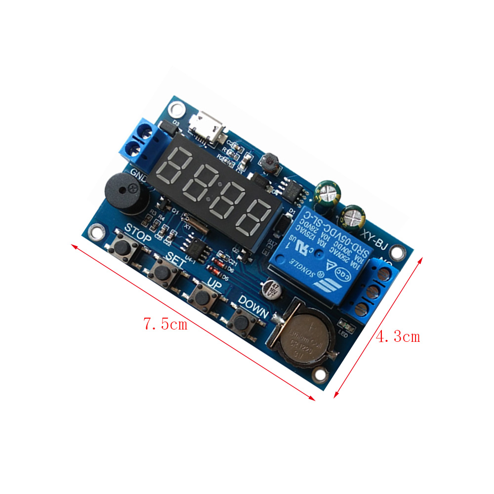
2. Please allow 1-3cm differences due to manual measurement.
Package Included:
1x Relay Module