1PC Adjustable power supply 0-30V 0-5A learning experiment power board stabilized constant current power board kit
model:
Board + all components
Without imported 3055 tube
Empty PCB board
10A100V red and blue dual display meter
Dual display head + red and black terminal
Without imported 3055 tube
Empty PCB board
10A100V red and blue dual display meter
Dual display head + red and black terminal
1. Please install 1A fuse for AC 220V incoming line
2. Try to stay away from the motherboard for the first time! Prevent the electric liberation cannon incident caused by various welding errors! ! !
3. The kit does not need to bring your own:
(1) 150W-180W transformer
Can be customized to specify the output value of 3 groups plus 15W-30W double 15V to make a transformer,
The most suitable for disassembling the machine with a bad power supply, or the 180W dual 14-16V of the power amplifier disassembly machine.
(2) Voltage and current meter head (3) Two TIP3055 heat sinks,
(4) 12v cooling fan (5) Cabinet and red and black binding posts
Simple circuit description:
L1 is the control part transformer,
A small 13V--18V 10-30W small transformer with a center tap can be selected.
This transformer can be independent, but it needs to be controlled by the same switch as L2.
L2 is the main transformer, which requires more power. 150W--180W
When outputting 30V, the suitable tap voltage is 0V-15V-23V-31V.
(Note that the rectified voltage must be within 50V! If the voltage is close to 50V, the main filter capacitor must be replaced with three 63V!)
The main transformer can also use the commonly used double-group middle tapped 13V--18V transformer. At this time, the relay RL2 may not be installed. But short the normally closed 2 pins of RL2.
note! ! ! The control power supply part is best to use dual 15V
25V2200 * 2 or 3300 * 2 for supporting electrolysis
In the circuit diagram, the main power supply leakage resistance is 7.5K for 2K 3W * 2
50V2200UF * 3 for main filtering (not more than 2200) or 63V2200 * 3
The two external potentiometers that regulate voltage and current can be replaced by multi-turns.
(Interpretation of changes: When the load is open or lightly loaded, there will be a relatively large overshoot when the original circuit is shut down.
1. To reduce the bleeder resistance of the main filter capacitor, 7.5K is reduced to 2k.
2. The purpose of increasing c1 and c2 to 2200uf or 3300uf is to control the power holding time of the circuit capacitor to be longer than the power holding time of the main filter capacitor, so as to prevent the control circuit (auxiliary circuit) from losing power and causing the main circuit output voltage to run out
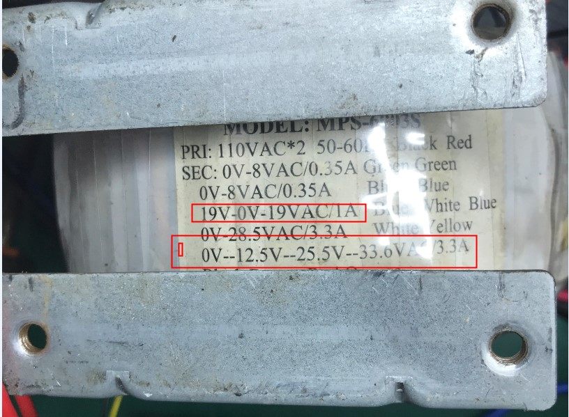
Attachment: Disassembly machine multi-winding transformer wiring reference diagram:
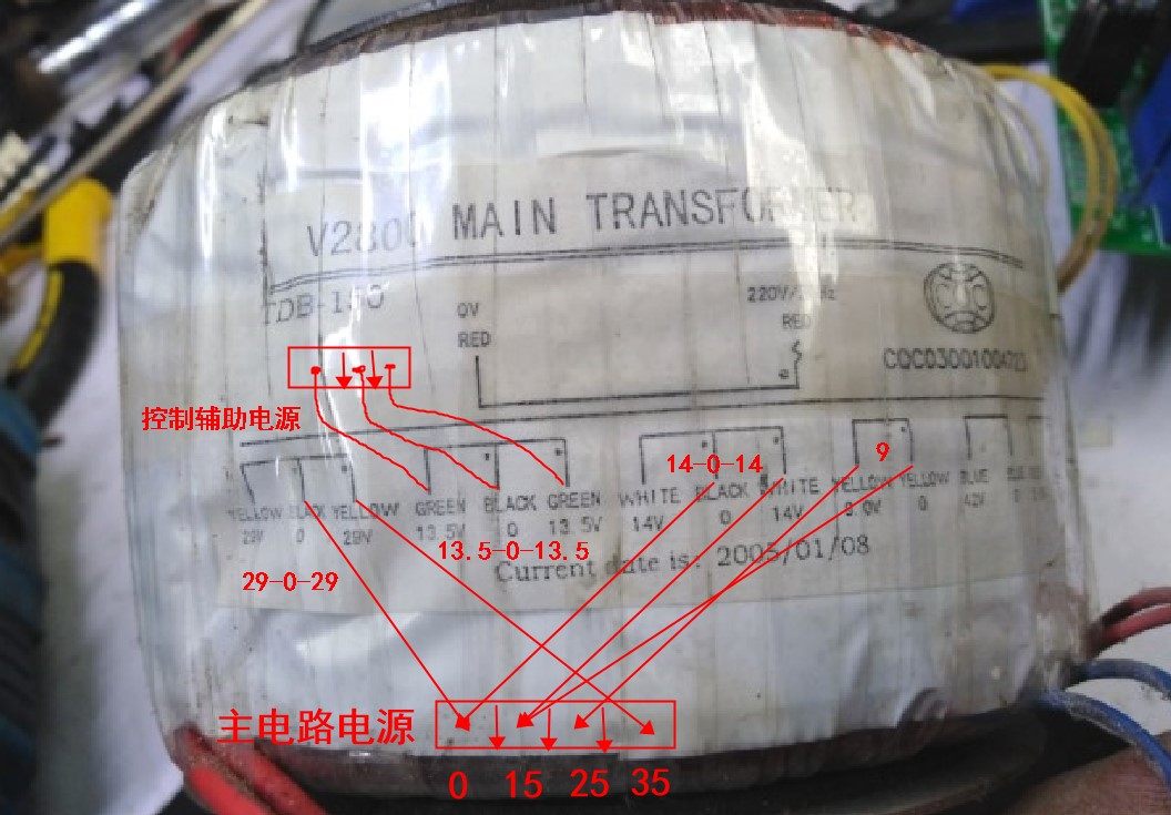
Below is an adjustable power disassembly transformer, the main winding is 0-12.5-25.5-33.6V directly available.
If the voltage after 33.5V filtering is too high, you can connect the 0-28.5 winding, 0 to the 0V terminal of the board,
28.5V connect to the 35V terminal on the board
The auxiliary winding is double 19V, if you want to use it, you need to replace 25V2200Uf with 35V2200Uf
The circuit diagram is as follows:

Full plug-in motherboard, size 10 * 10CM
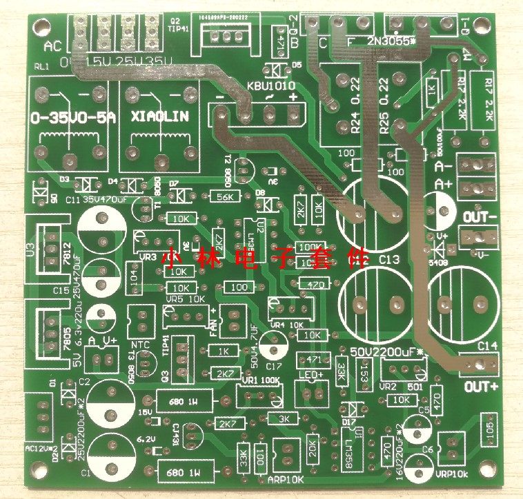
All of the kit:

Welding reference drawing:

Use a dual 12V main output transformer to make a 0-25V 0-5A, equipped with peripheral accessories as shown in the figure:
note! Do not refer to the 1602 digital header wiring! ! !
It's a voltage and current test line. Not the same as the dual-display digital header
The connection method of the dual display head is:
OUT + and OUT- on the board are the main power output connected to the red and black binding posts
The A + A- terminal is connected to the thick red black of the digital meter, and the 5V output next to 7805 is connected to the thin red black line of the meter
The small letter V + connects to the thin yellow line of the header (V- is connected to the negative electrode of the pointer)
NTC is connected to the thermistor FAN is connected to the cooling fan

Peripheral connection diagram:

Responsibility statement:
Since the product is provided as a kit, the kit also needs to be assembled by itself, including electronic components soldering, circuit debugging, etc. are complex actions that require experience.
This kit provides all components and circuit schematics, but the transformer, housing, voltage and current meter need to be prepared by the user! The user must understand that failures due to unsuccessful assembly may be caused by various unexpected reasons and bear the losses on their own.
Electronic products are closely related to electricity, please confirm whether to purchase according to your electronic production capabilities,
This kit does not provide any technical support, please carefully read the kit schematic diagram and related debugging instructions before purchasing, and confirm that you can complete the independent debugging before buying, thank you for your cooperation!
About the principle, characteristics and use of adjustable constant voltage and constant current power supply:
The principle of constant pressure and constant current:
According to U = IR, R = U / I:
If R> (U / I), the power supply is working normally.
If R <(U / I), I is constant, the power supply constant current part is protected, and the output voltage drops until the condition R = (U / I) is met.
According to U = IR, R = U / I:
If R> (U / I), the power supply is working normally.
If R <(U / I), I is constant, the power supply constant current part is protected, and the output voltage drops until the condition R = (U / I) is met.
characteristic:
The so-called constant voltage, that is, the voltage can be constant to a value, adjustable constant voltage, that is, this constant voltage value is adjustable.
The so-called constant current, that is, the current can be constant to a value, adjustable constant current, that is, this constant current value is adjustable.
use:
The adjustable constant voltage constant current power supply needs to set the constant current protection value before use, and then set the output voltage, and then start working.
First adjust the output voltage of the power supply to about 5V, short-circuit the output, adjust the current output knob to set the protection current to the value you need, cancel the short circuit, adjust the voltage to the required value, connect the experimental equipment and start working.
For example, the working voltage of a circuit is about 0.3A at 12V, and the operation is as follows.
Adjust the output voltage of the power supply to about 5V, short circuit output, adjust the current output knob to set the protection current 0.5A (slightly larger than the operating current), cancel the short circuit, adjust the voltage to 12V, connect the circuit and start the experiment.
If the circuit board is placed on the metal during the test, part of the circuit is short-circuited, so that the current increases sharply. When the current rises to 0.5A, the power supply constant current protection part works even if the output voltage drops to protect the test equipment.
Common sense:
After the AC voltage is filtered by the full-wave rectifier capacitor, the DC voltage is about 1.414 times the AC voltage.
For example, after the AC voltage of 10V is filtered by the full-wave rectifier capacitor, the DC voltage is approximately equal to 14V. Selection of relay switching point:
The AC input voltage minus 5V equals the switching voltage.
For example, transformer tap 0-15V-25V-35
Then the switching voltage of the first stage is 15V-5V = 10V, that is, switching to the 25V tap at 10V.
The switching voltage of the second stage is 25V-5V = 20V, that is, it is switched to the tap of 35V at 20V.
Regarding whether the relay is switched or not, it can be judged by measuring the voltage across R17. The voltage of R17 (DC) divided by 1.414 is approximately equal to the current tap voltage (AC).
Preparation before commissioning:
After the installation is checked and checked (the capacitor and diode on the output must be installed; TIP3055 must be installed on a large radiator), if you do not connect the ammeter, please short-circuit the ammeter contact "A", and then power on.
Please refer to the schematic diagram:
Measure C1, C2 voltage, should be normal at 12-25V.
Measure C11 voltage, less than 30V is normal.
Measure C15 voltage, 12V is normal.
If the above voltage is abnormal, please check whether the transformer is powered, whether the taps are connected incorrectly, and whether the components are installed incorrectly. Repeat the above steps until the voltage is normal.
Commissioning process:
Adjust VR3 and VR4 so that the voltage of pins 2 and 6 of U2 chip is above 10V
Adjust VR3 and VR4 so that the voltage of pins 2 and 6 of U2 chip is above 10V
(Take U4's 4 feet as reference point).
The voltage across R17 should be the voltage after the first-stage tap rectification and filtering of the transformer.
The A-RP current knob is adjusted to the middle, and the constant current indicator LED1 should not be lit at this time.
Adjust the V-RP, the voltage can be adjusted around 0-18V (R17 voltage) is considered normal.
The output voltage is adjusted to the voltage of the first stage relay switching point
packing: 1PC
warranty period: 120 days
Am 23.08.21 hat der Verkäufer die folgenden Angaben hinzugefügt:
