Fast shipping to US!
This item will be shipped from US local warehouse by UPS. US Customers (except for Alaska, Hawaii & Puerto Rico) will receive this item fastly.
The more importance is that US customers dont need to pay Import Custom duty & fees. (Becuase it is domestic shipping)
This item includes:1 pcs Nema 34 stepper motor 1700 oz.in 6A with single Shaft1 pcs Stepper motor driver, DM860A, peak 7.8A ,256 Micsteps,replacing M8601 pcs Power Supply 350W-60VDC1 pc Breakout Board & 1 pc parallel cable
Features:
1.High torque, More smooth movement
2.High efficiency, energy-saving, low noise, low vibration, high start torque, low start current and reliable performance.
3.We offfer mach 3 software by free,if you want please download on our website.
After you payment,I will send electronic manual to your e-mail,if you not receive,you tell me your e-mail,I will send to you.
Detailed information :
1. Nema 34 stepper motor:
Technical Specifications
Part No.: 34HS5460
Frame Size: NEMA34
Phase: 2 Phase
Step Angle: 1.8 degree
Current: 6 A
Rated Voltage: 3.6 V
Resistance: 0.6 Ohm/phase
Inductance: 8 mH/phase
Holding torque: 1700oz-in (12 N.m)
Detent torque: 24.5N.cm
Rotor inertia: 4000 g.cm²
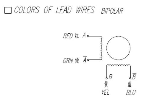
Number of wire leads: 4 (Red A+ ,Green A- ,Yellow B+ ,Blue B-)
Weight: 5kg
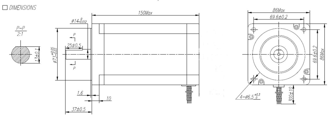
Length: 151mm
Front shaft length 37mm
The diameter for motor shaft is 14mm
Matched drive:DM860A
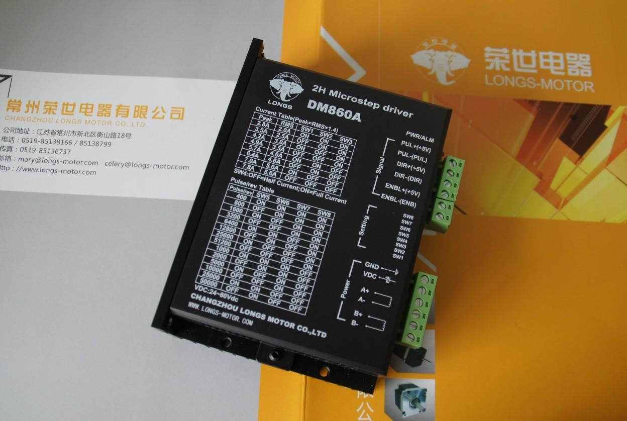
Input voltage | 24-80VDC |
Input current | < 6A |
Output current | 2.8A~7.8A |
Consumption | Consumption:80W; Internal Insurance:10A |
Temperature | Working Temperature -10~45℃; Stocking temperature -40℃~70℃ |
Humidity | No condensation, no water droplets |
gas | Prohibition of combustible gases and conductive dust |
weight | 500G |
| Pin Function | Details |
| PUL +,PUL- | Pulse signal, PUL+ is the positive end of pulses input pin PUL- is the negative end of pulse input pin |
| DIR+,DIR- | DIR signal: DIR+ is the positive end of direction input pin DIR- is the negative end of direction input pin |
ENBL+ | Enable signal: ENBL+ is the positive end of direction input pin. This signal is used for enabling/disabling the driver. High level for enabling the driver and low level for disabling the driver. |
| ENBL- | ENBL- is the negative end of direction input pin. Usually left unconnected (enabled) |
SW5 | ON | OFF | ON | OFF | ON | OFF | ON | OFF | ON | OFF | ON | OFF | ON | OFF |
SW6 | ON | ON | OFF | OFF | ON | ON | OFF | OFF | ON | ON | OFF | OFF | ON | ON |
SW7 | ON | ON | ON | ON | OFF | OFF | OFF | OFF | ON | ON | ON | ON | OFF | OFF |
SW8 | ON | ON | ON | ON | ON | ON | ON | ON | OFF | OFF | OFF | OFF | OFF | OFF |
PULSE/REV | 400 | 800 | 1600 | 3200 | 6400 | 12800 | 25600 | 51200 | 1000 | 2000 | 5000 | 10000 | 25000 | 50000 |
Output current (A) | ||||
SW1 | SW2 | SW3 | PEAK | RMS |
ON | ON | ON | 2.80 | 2.00 |
OFF | ON | ON | 3.50 | 2.50 |
ON | OFF | ON | 4.20 | 3.00 |
OFF | OFF | ON | 4.90 | 3.50 |
ON | ON | OFF | 5.70 | 4.00 |
OFF | ON | OFF | 6.40 | 4.60 |
ON | OFF | OFF | 7.00 | 5.00 |
OFF | OFF | OFF | 7.80 | 5.60 |
| Motor and power pins | 1 | A+ | Motors wiring | |
2 | A- | |||
3 | B+ | |||
4 | B- | |||
5,6 | DC+ DC- | Power supply | Power supply :DC24-80VDC The peak input current can not up to 6A |
PWR: green, normal work light.
ALM: red, failure light, the motor with phase short-circuit, overvoltage and under-voltage protection.
Alarm indicator | Reasons | Measures |
LED off turn | Wrong connection for power | Check wiring of power |
Low-voltages for power | Enlarge voltage of power | |
Motor doesn’t run, without holding torque | Wrong connection of stepper motor | Correct its wiring |
RESET signal is effective when offline | Make RESET ineffective | |
Motor doesn’t run, butmaintains holding torque | Without input pulse signal | Adjust PMW & signal level |
Motor runs wrong direction | Wrong wires’ connection | Change connection for any of 2 wires |
Wrong input direction signal | Change direction setting | |
Motor’s holding torque is too small | Too small relative to current setting | Correct rated current setting |
Acceleration is too fast | Reduce the acceleration | |
Motor stalls | Rule out mechanical failure | |
Driver does not match with the motor | Change a suitable driver |
3.Power Supply
350W-60V
4. Breakout Board & 1 pc parallal cable
General in the software
P2 P3 is set to X-axis for the X-axis pulse
P4 P5 is set to Y-axis, Y axis pulse
P6 P7 is set to Z-axis Z-axis pulse
The other can be set to A B C axis
A-axis pulse P8 P9 is set as the A axis
P14 is set to B-axis B-axis pulse P1
P16 P17 is set to C-axis, C axis pulse
Can also be set to the spindle control signal \ electrical permit
Input interface for the P10 P11 P12 P13 P15
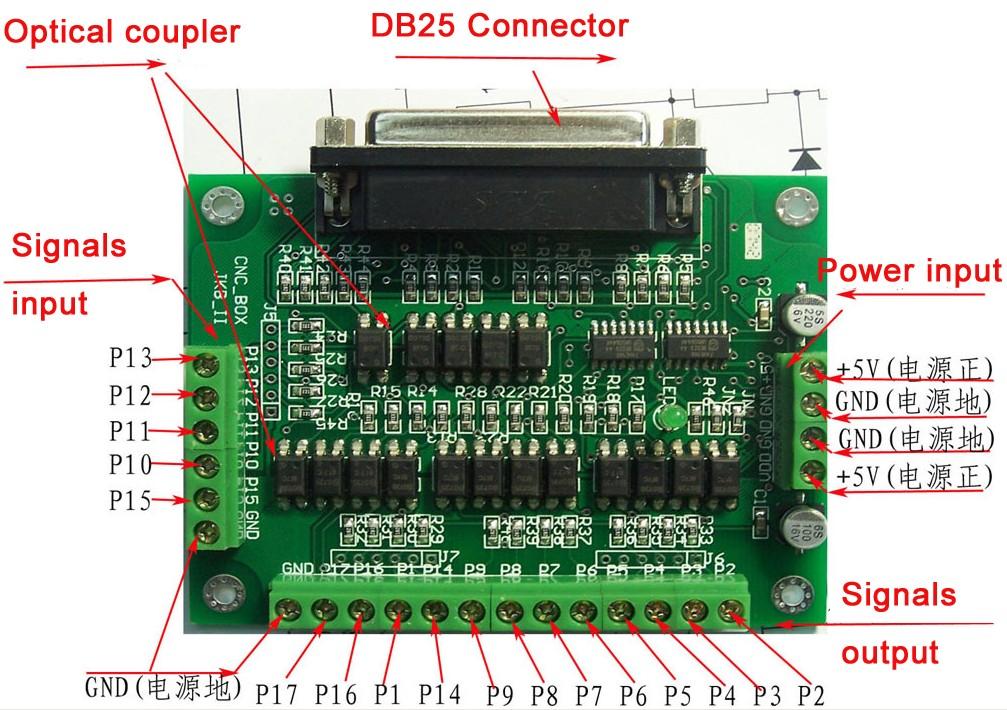
• Built in DB25 male connector.
• DB25 Output Pin:P1,P2,P3,P4,P5,P6,P7,P8,P9,P14,P16,P17.
• DB25 Input Pin: P10,P11,P12,P13,P15.
• DB25 GND Pin: P18-P25.
• Power supply: +5V DC.
• Built in C-class Optical-coupler.
• High quality with Surface-mount Tech.
Application:Our Stepper Motors are used on small to mid-sized CNC mills or milling machines,
CNC lathes, Pick-n-place machines,Laser Engravers and Laser Cutters, Vinyl Sign Cutters,
CNC Plasma Cutters, and CNC Foam Cutters. Carver machine ,Dispenser,Automazation,
3D Printer,Stage lighting,instrument,laser equipment,scanner and so on.These motors have been
used in precision telescope positioning systems and robots.