Tasmota Dual RS232 seriell to WLan RS232 Sniffer Modul Bausatz serial to WiFi Module Kit Set inkl. Firmware |
|||||||||||||||||||||||||||||||||||||||||||||||||||||||||||||||||||||||||||||||||||||||||||||||||||||||||
EI-OT ESP8266 dual RS232 WiFi Bridge Module © ei-ot ® 
EI-OT ESP8266 Dual RS232 WiFi Bridge Module Kit © ei-ot ® 
EI-OT ESP8266 Dual RS232 WiFi Bridge Module Assembling © ei-ot ® 
EI-OT ESP8266 RS232 WiFi Bridge Module Dimensions © ei-ot ® 
EI-OT ESP8266 RS232 WiFi Bridge Module ESP-01+ Tasmota Firmware © ei-ot ® 
EI-OT ESP8266 RS232 WiFi Bridge Module connecting © ei-ot ® 
EI-OT ESP8266 Dual RS232 WiFi Bridge Module Tasmota Firmware © ei-ot ® 
EI-OT ESP8266 Dual RS232 WiFi Bridge Module Example © ei-ot ® 
EI-OT ESP8266 RS232 WiFi Module Sniffer Mode Example © ei-ot ® 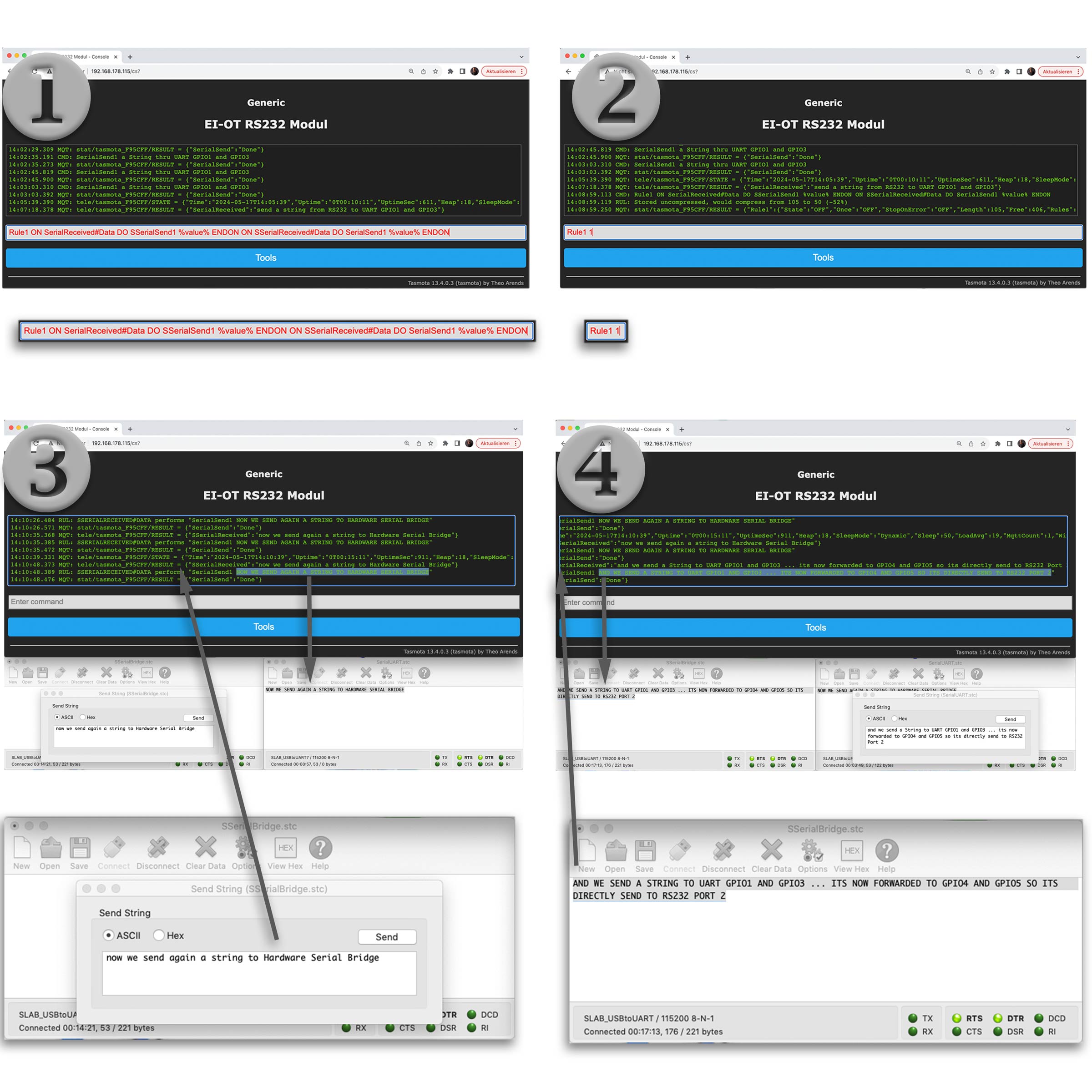
|
Der EI-OT RS232 WiFi Bridge Modul Bausatz in der neusten Version erlaubt die direkte WLan Anbindung von 2 Geräten die über eine RS232 Schnittstelle verfügen. Das dual RS232 verfügt nun über 2 RS232 Schnittstellen:
Bedarf es eines direkten virtuellen COM Port, empfiehlt sich der kombinierte Einsatz mit dem USB TTL virtuellen COM Port WLan Modul. Funktionsprinzip
Typische MCU's, so auch der ESP8266 unterstützen lediglich einen 3,3V UART Level, diesbezüglich wurde beim RS232 dual WiFi Bridge Modul die
Das EI-OT dual RS232 WiFi Bridge Modul basiert auf dem ESP8266 ESP-01+. Der ESP8266 ESP-01+ verfügt über einen 32Mbit SPI Flash Speicher und erlaubt dank Tasmota Firmware eine einfache Integration in WLan Netzwerke. Bedingt durch den reduzierten Platzbedarf des ESP-01+, konnte die Hauptplatine des dual RS232 WiFi Bridge Modul entsprechend kompakt realisiert werden.
Die Hauptplatine
des EI-OT dual RS232 ESP8266 WiFi Bridge Modul Bausatz verfügt bereits über grundlegende SMD Komponenten wie
Dual RS232 WiFi Bridge Modul Bausatz Lieferumfang
Neben der Hauptplatine sind im EI-OT dual RS232 ESP8266 WiFi Bridge Modul Bausatz folgende Komponenten enthalten:
Dual RS232 WLan Bridge Modul basierend auf dem ESP-01+ bereits mit Tasmota geflasht GPIO und weitere Anschlüsse
Auf der Hauptplatine des dual RS232 WLan Bridge Modul Bausatz wurden zusätzlich folgende Anschlüsse
Die Tasmota Firmware des dual RS232 ESP8266 WiFi Bridge Moduls wurde speziell auf die Übertragung von seriellen Daten optimiert und verfügt neben den erforderlichen Bibliotheken zusätzlich über
|
The latest version of the EI-OT RS232 WiFi bridge module kit allows the direct WiFi connection of 2 devices that have an RS232 interface. The dual RS232 now has 2 RS232 interfaces:
Working Principle
Typical MCU's, also the ESP8266 supporting only 3,3V UART Level, therefore the ESP8266 Modul is connected to a UTC3232 Level Converter IC to support
with serial data. In Combination with appropriate capacitors, the UT3232 converts a RS232 Level from ±13V to required 3.3V Level of EPS8266 serial level. In Combination with the Tasmota Firmware
The PCB
of the EI-OT dual RS232 ESP8266 WiFi Bridge Module Kit comes assembled with basic SMD components such as
Dual RS232 WiFi Bridge Module Kit
besides the basic PCB the EI-OT dual RS232 ESP8266 Module Kit includes:
Dual RS232 WiFi Bridge Module based on ESP-01+ Tasmota Firmware flashed GPIO additionally Connections
The EI-OT RS232 WiFi Bridge Module Board features
The Tasmota Firmware of the RS232 ESP8266 WiFi Bridge Module is optimized to transfer serial Data. Besides basic Libraries the Tasmota Firmware supports
|
|||||||||||||||||||||||||||||||||||||||||||||||||||||||||||||||||||||||||||||||||||||||||||||||||||||||
|
|||||||||||||||||||||||||||||||||||||||||||||||||||||||||||||||||||||||||||||||||||||||||||||||||||||||||
| EI-OT dual RS232 WiFi Bridge Module Board assembling |
EI-OT dual RS232 Modul bestücken
Das EI-OT dual RS232 WLan Bridge Modul ist bereits mit SMD Komponenten wie
Zur Inbetriebnahme müssen lediglich, nachfolgende Komponenten wie in nebenstehender Grafik dargestellt bestückt / verlötet werden. Die Bestückung des dual RS232 WLan Bridge Moduls Schritt für Schritt:
|
EI-OT dual RS232 Module assembling
The EI-OT dual RS232 WiFi Bridge Module is already equipped with SMD components such as
|
EI-OT ESP-01+ ESP8266 RS232 Module Jumper Setting  |
Jumper setzen
Nach entsprechender Bestückung verfügt das Modul über eine DB9 (female) Anschlussbuchse. Dementsprechend sind die Pins des DB9 Anschluss wie folgt belegt:
Dementsprechend müssen die RS232 Signale zu 3232 Level Shifter IC mittels Jumper gemäß nebenstehender Grafik gesetzt werden. An dieser Stelle sei erwähnt (leider ein sehr häufiger Fehler) der einfache Wechsel durch Kreuzen der Pin's auf einen DB Stecker funktioniert nicht! Im Detail wird hierzu der Pin4 des DB9 benötigt, dieser ist nicht belegt. Rein theoretisch könnte man aber einen DB9 Male Anschluss auf der Unterseite der Platine platzieren. |
Jumper setting
After appropriate assembly, the module has a DB9 (female) connection socket. Accordingly, the pins of the DB9 connection are assigned as follows:
|
| EI-OT dual RS232 Module connection |
Spannungsversorgung
Die zentrale Spannungsversorgung erfolgt über die Pins
Anschluss RS232 - 2
Der zweite RS232 Anschluss erfolgt über die 7-polige Pinleiste
|
Power Supply
The central voltage supply is provided by
Power Supply
The second RS232 interface is provided by Pin Header
|
| EI-OT dual RS232 Module attach ESP-01+ ESP8266 Module |
ESP-01+ Modul aufstecken
Nachdem die benötigten Anschlüsse hergestellt wurden, muß lediglich das ESP-01+ Modul auf den Stecksockel aufgesteckt werden. |
attach ESP-01+ Module
After the required connections have been made, the ESP-01+ module simply needs to be plugged into the socket. |
Tasmota WLan WiFi Configuration |
Tasmota WLan Konfiguration
Die Tasmota Firmware erlaubt eine einfache WLan Konfiguration mittels Webinterface. An dieser Stelle sei erwähnt, die Tasmota Firmware unterstützt den SoftAP Modus (Access Point) lediglich zur WLan Konfiguration. Sobald das jeweilige Modul als Client in einem bestehenden Netzwerk eingebunden wurde, wird der SoftAP Modus nicht mehr unterstützt. Tasmota Client Anbindung mittels Webinterface
Nachdem das jeweilige Modul mit Spannung versorgt wurde startet das Modul im SoftAP Modus. Innerhalb der Netzwerkumgebung eines
Die WLan Konfiguration mittels dem Tasmota Webinterface erfolgt mittels 5 einfachen Schritten:
Behebung etwaiger Probleme
Sollte man die IP Adresse vergessen haben, kann diese üblicherweise im Webinterface des Routers unter Netzwerk oder WLan gefunden werden. Bei falschen WLan / Netzwerk Parametern, z.B. falschem Passwort wird die Verbindung seitens des Routers abgewiesen. Dementsprechend muss das Tasmota Modul mittels Factory Default Reset wie folgt zurückgesetzt werden
|
Tasmota WiFi Configuration
The Tasmota firmware allows simple WiFi configuration thru Browser web interface. At this point it should be mentioned that the Tasmota firmware only supports SoftAP mode (access point) for WiFi configuration. As soon as a Tasmota module has been integrated as a WiFi client in an existing network, SoftAP mode is disabled. Tasmota WiFi Client Setup
After Tasmota module has been supplied with voltage, the module starts as Tasmota SoftAP. Within network environment of
Troubleshooting
In case of IP address was lost it can usually be found in the router's web interface under Network or WiFi. In case of WiFi / network parameters are incorrect, e.g. an incorrect SSID Name or password, the connection will be rejected by the router. Accordingly, the Tasmota module must be reset using a factory default reset as follows
|
| EI-OT ESP8266 RS232 RX TX serial Bridge Configuration |
Tasmota Konfiguration
Nachdem die WLan Konfiguration durchgeführt wurde, kann das dual RS232 Modul innerhalb Tasmota wie folgt konfiguriert werden:
|
Tasmota Configuration
After the WiFi configuration is finished, the dual RS232 WiFi Bridge Module must be configured as follows:
|
RS232 over TCP thru WiFi USB/TTL serial Bridge 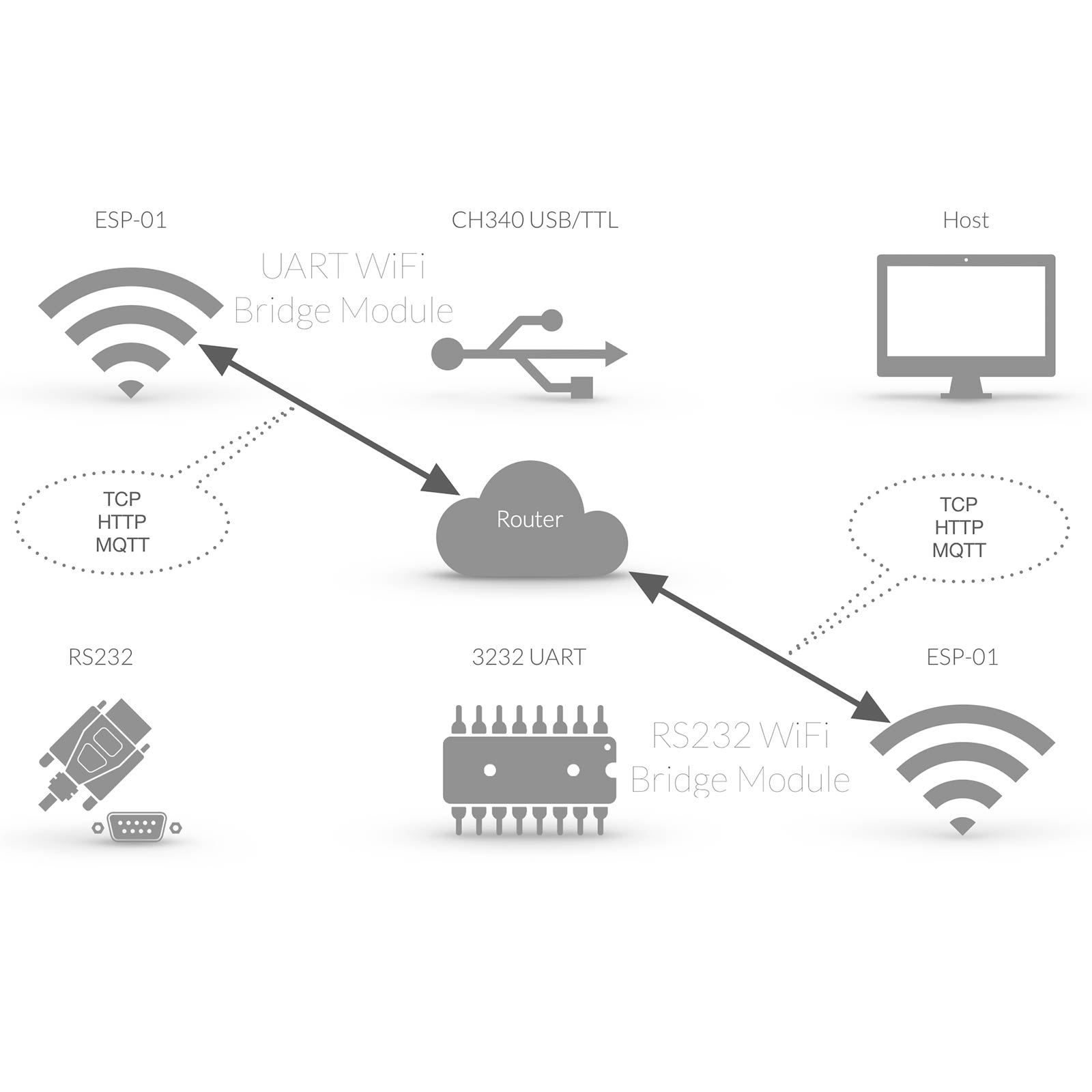 |
RS232 COM Schnittstelle
Die RS232 Schnittstelle hat ihren Ursprung in den 1960er Jahren und wird mittlerweile häufig durch den Universal Serial Bus ersetzt. Dementsprechend verfügen viele PC's und auch Notebooks über keine physische RS232 Schnittstelle mehr, eine serielle Datenübertragung erfolgt meist über USB (Universal Serial Bus). Bei MAC's ist generell keine RS232 / COM Schnittstelle mehr verfügbar. Da RS232 aber häufig zur Anbindung von Endgeräten Anwendung findet, bedarf es meist entsprechender RS232 / USB Konverter.
Vorteil dieser kabelgebundenen RS232 Verbindung ist die Herstellung eines "physischen", im Detail virtuellen COM Port. Der virtuelle COM Port wird dabei direkt in dem jeweiligen Betriebssystem bereitgestellt, bzw. kann direkt in einer Software angesprochen werden.
Neben der kabelgebundenen RS232 Anbindung kann gleichermassen ein virtueller COM Port über WLan realisiert werden.
Im nachfolgenden Tutorial wird mittels
|
RS232 COM Interface
The RS232 COM Interface is a standard originally introduced in 1960 for serial communication transmission of data. Meanwhile most Computers are based on other serial Interface such as USB (Universal Serial Bus). Because of RS232 Standard often RS232 is used to connect Devices to Computers thru RS232 / USB Converter.
Advantage of a wired RS232 connection is a "physical", in Detail virtual COM Port. The virtual COM Port is directly available thru Operating System and is available in Software Applications.
Besides the wired RS232 Connection, a virtual COM Port can be realized thru WiFi.
In our tutorial we describe a RS232 Connection thru WiFi and a virtual COM Port
|
Tasmota TCP COM Port Configuration  |
Tasmota Konfigurieren
Nun muss das EI-OT Dual RS232 Modul noch entsprechend mittels der Tasmota Weboberfläche konfiguriert werden, sodass RS232 Signale direkt auf TCP umgesetzt werden. In diesem Beispiel wird die zweite RS232 Schnittstelle des EI-OT dual RS232 Moduls, also GPIO4 und GPIO5 verwendet und entsprechend innerhalb der Tasmota Firmware wie folgt konfiguriert:
|
Tasmota Configuration
Now the EI-OT Dual RS232 module must be configured accordingly using the Tasmota web interface so that RS232 signals are converted directly to TCP. In this example, the second RS232 interface of the EI-OT dual RS232 module, i.e. GPIO4 and GPIO5, is used and configured accordingly within the Tasmota firmware as follows:
|
RS232 Tasmota serial TCP COM Port Configuration  |
TCP COM Port Konfigurieren
Im Eigentlichen ist die Anbindung einer virtuellen COM Schnittstelle über WLan und Tasmota TCP Socket einer typischen COM Port Anbindung gleichzusetzen. Im Detail Bedarf es dabei der typischen Konfiguration der seriellen Schnittstelle die mittels Konsole und Kommandozeilen Eingabe wie folgt konfiguriert wird
|
TCP COM Port COnfiguration
Compared to a regular COM Port connection there is no big difference to a Tasmota TCP Socket based COM Port connection. It requires also typical COM Port / Interface Parameter configuration such as
|
Tasmota ESP8266 UART RX TX standard communication  |
serieller Befehlssatz
Zusammenfassend läßt sich die Tasmota Befehlssatz zur seriellen Kommunikation über die UART Schnittstelle eines ESP8266 sowie ESP32 von jedem typischen seriellen Terminal Programm ableiten. Grundlegend basieren die folgenden Parameter auf typische serielle Schnittstellen.
Ganz gleich ob es sich bei der Hardware um ein
Baudrate 115200setzt die Baudrate auf 115200 SerialBuffer, fragt den aktuellen seriellen Buffer / Speicher ab, bzw. setzt den aktuellen Speicher durch Eingabe des jeweiligen Parameters (von 256 bis 520), Beispiel SerialBuffer 520setzte den Speicher auf 520 Byte. SerialConfig, fragt das aktuelle serielle Protokoll (Datenbits, Parität, Stopbits) ab, bzw. konfiguriert das serielle Protokoll. beispielsweise SerialConfig 8N1setzt das serielle Protokoll auf Datenbits 8 Parität None (Keine) Stopbits 1 SerialDelimiter, fragt den ASCII Dezimal Code des aktuell festgelegte Steuerzeichens ab, bzw. konfiguriert das Steuerzeichen durch anhängen des jeweiligen Dezimal ASCII Code, beispielsweise SerialDelimiter 13setzt CR (Carriage Return) als Steuerzeichen. Das jeweilige Steuerzeichen wird dabei gemäß ASCII Dezimal Zeichensatz interpretiert. Neben der expliziten Zuweisung des Steuerzeichens (von 0-127) kann zusätzlich 128, erlaubt lediglich ASCII Zeichen vom Dezimalwert 32 bis 127 254, deaktiviert sowohl das Steuerzeichen, als auch eine voran gestellten Hex String 255, deaktiviert das Steuerzeichen (es wird 1:1 übertragen) serielle Kommunikation
Die serielle Kommunikation erfolgt über die Tasmota Konsole. Serielle Datenpakete werden dabei mittels SerialSend übertragen und mittels SerialReceived in der Console ausgegeben. Zur richtigen Interpretation der seriellen Daten werden 6 Optionen zur Übertragung bzw. Interpretation der seriellen Daten bereitgestellt. Mit einfachen Worten, die empfangenen werden stets im Datenformat der zuvor gesendeten Datenart interpretiert / in der Konsole ausgegeben.
|
serial instruction set
In summary, the Tasmota command set for serial communication via the UART interface of an ESP8266 and ESP32 can be derived from any typical serial terminal program. Basically, the following parameters are based on typical serial interfaces.
Regardless of whether the hardware is a
Baudrate 115200sets Baudrate to 11520 SerialBuffer, queries actual Buffer Size, SerialBuffer in combination with a Buffer Size (from 256 up to 520) sets the Buffer Size, for example SerialBuffer 520configures Buffer Size to 520 Byte. SerialConfig, queries actual serial Protocol (Data bits, Parity, Stop bits) in combination with valid 3 parameters for example SerialConfig 8N1configures serial protocol to Data bits 8 Parity None Stop bits 1 SerialDelimiter, queries actual Serial Delimiter ASCII Decimal Code in combination with a valid ASCII Decimal Code is set to new Serial Delemitter, for example SerialDelimiter 13enables CR (Carriage Return) as Serial Delimiter. Beside a ASCII Decimal Value (0-127) following are valid 128, only allow ASCII characters 32 to 127 in response text 254, disable serial delimiter and post HEX string 255, disable serial delimiter serial Communication
For direct communication use Command Line of Tasmota Console. The serial Data are send thru serial command SerialSend and incoming datas are shown as SerialReceived. For correct serial data interpretation are 6 options available. In simple Words, received Data are always interpreted in same format as serial data was previously send.
|
EI-OT RS232 Module dual mode connection  |
Tasmota RS232 Anschluß
Insofern keine GPIO Konfiguration festgelegt wurde, wird innerhalb der Tasmota Firmware GPIO1 als UART TX und GPIO3 als UART RX definiert. Im nachfolgenden Beispiel wird zusätzlich GPIO4 als serBr TX und GPIO5 als serBr RX (zweite RS232 Schnittstelle mittels Tasmota Hardware Bridge) verwendet. Als Hardware werden 2 echte CP2102 RS232 Level Konverter verwendet, sollten beispielsweise USB/TTL Konverter verwendet werden erfolgt zwar eine Kommunikation, jedoch erscheinen unleserliche Zeichen im seriellen Terminal (da das EI-OT RS232 Modul echten RS232 Level liefert). Ferner wird ein entsprechender serial Terminal benötigt, im nachfolgenden Beispiel Roger Meier's Freeware CoolTerm. |
Tasmota RS232 Connection
If no GPIO configuration has been specified, GPIO1 is defined as UART TX and GPIO3 as UART RX within the Tasmota firmware. In the example below, GPIO4 is also used as serBr TX and GPIO5 as serBr RX (second RS232 interface using Tasmota Hardware Bridge).
Two real CP2102 RS232 level converters are used as hardware. If, for example, USB/TTL converters are used, communication takes place, but illegible characters appear in the serial terminal (since the EI-OT RS232 module delivers real RS232 level). |
| Tasmota RS232 Module dual mode example |
Tasmota RS232 Beispiel
Nachdem wie oben benannt
|
Tasmota RS232 Example
After as named above
|
RS232 dual Module Sniffer Bridge Mode  |
RS232 Sniffer Modus
Sniffer zu Deutsch Schnüffler Modus beschreibt im Eigentlichen bereits den Sniffer Modus.
Seit mittlerweile über 20 Jahren hat der USB (Universal Serial Bus) die typische serielle Anbindung mittels RS232 am typischen Computer weitestgehend abgelöst. Dementsprechend kann die Anbindung eines Gerätes mit RS232 Schnittstelle eine gewisse Herausforderung darstellen. Oftmals wird zu günstigen USB TTL Konvertern gegriffen um ein RS232 Signal auf eine USB Schnittstelle umzusetzen. Insofern das Endgerät seine RS232 Schnittstelle mit 5V Level betreibt (sehr unwahrscheinlich / dann wäre es keine RS232 Schnittstelle) kann das sogar funktionieren.
Da das EI-OT dual RS232 Modul jedwede Signale auf WLan umsetzt ist die Anbindung an jedweden Computer, oder sonstiges Endgerät mit WLan Schnittstelle möglich.
Was aber wenn die RS232 Schnittstelle von 2 Endgeräten genutzt wird, mit einfachen Worten wenn 2 Geräte über eine RS232 Schnittstelle kommunizieren.
Hier kommt typischerweise ein Sniffer zum Einsatz, dabei werden sämtliche Daten an beide RS232 Teilnehmer / Geräte durchgereicht und sämtliche Daten protokolliert, im Detail auf ein weiteres Protokoll übersetzt. |
RS232 COM Interface
For over 20 years now, the USB (Universal Serial Bus) has largely replaced the typical serial connection using RS232 on the typical computer. Accordingly, connecting a device with an RS232 interface can be a certain challenge. Cheap USB TTL converters are often used to convert an RS232 signal to a USB interface. To the extent that the end device operates its RS232 interface with a 5V level (very unlikely / then it would not be an RS232 interface) it can even work.
Since the EI-OT dual RS232 module converts any signals to WiFi, it can be connected to any computer or other device with a WiFi interface.
But what if the RS232 interface is used by 2 end devices, in simple words if 2 devices communicate via one RS232 interface.
A sniffer is typically used here, all data is passed on to both RS232 participants/devices and all data is logged and translated in detail into another protocol. |
| RS232 serial Sniffer Mode Configuration |
RS232 Sniffer Konfigurieren
Zwar verfügt das EI-OT dual RS232 Modul über 2 RS232 Schnittstellen, jedoch funktionieren beide Schnittstellen unabhängig voneinander. Die Grundlage für einen RS232 Sniffer wird im eigentlich schon durch den typischen RS232 Anschluss transparent:
Rule1 ON SerialReceived#Data DO SSerialSend1 %value% ENDON ON SSerialReceived#Data DO SerialSend1 %value% ENDON
Nachfolgend die einfache Konfiguration des RS232 Sniffer Modus
|
RS232 Sniffer Configuration
Although the EI-OT dual RS232 module has 2 RS232 interfaces. Both interfaces normally work independently of each other. The basis for an RS232 sniffer is actually made clear by the typical RS232 connection:
Rule1 ON SerialReceived#Data DO SSerialSend1 %value% ENDON ON SSerialReceived#Data DO SerialSend1 %value% ENDON
Below is the simple configuration of the RS232 sniffer mode
|
Tasmota Telemetrie Clients MQTT infrastructure  |
HiveMQ MQTT
Im folgenden Beispiel zur MQTT Anbindung eines Tasmota Moduls wird zwar HiveMQ als MQTT Broker verwendet, im Grunde ist die Einbindung innerhalb Tasmota stets identisch.
Grundlegend basiert die Tasmota MQTT Anbindung auf den typischen Parametern
#define USE_MQTT_TLS
aktiviert sein.
Oftmals wird ein MQTT Broker fälschlicherweise auch als ein "Server mit einem Webinterface" beschrieben. Ein MQTT Broker ist lediglich als Vermittler zwischen einer Vielzahl verschiedener Teilnehmer zu verstehen. Das ganz basiert dabei auf einer einfachen Grundlage es wird
|
HiveMQ MQTT
In the following example of the Tasmota Module MQTT connection HiveMQ is used as the MQTT broker, but the integration within Tasmota is basically always identical.
The Tasmota MQTT connection is fundamentally based on the typical parameters
#define USE_MQTT_TLS
be activated.
An MQTT broker is often incorrectly described as a “server with a web interface”. An MQTT broker is simply to be understood as an intermediary between a large number of different participants. This is all based on a simple basis
|
HiveMQ MQTT Broker Cluster setup  |
MQTT Broker einrichten
Die Einrichtung eines MQTT Brokers unter HiveMQ ist denkbar einfach.
Zunächst, insofern man noch nicht über ein HiveMQ Benutzerkonto verfügt muss man sich hier entsprechend registrieren, bzw. anmelden.
Nachdem man sich registriert und angemeldet hat wird man direkt auf die Cluster Verwaltung geleitet, hier lediglich den Button CREATE NEW CLUSTER klicken.
Es erscheint die Übersicht der verfügbaren Cluster Pakete, hier das Paket Serverless FREE durch klick auf Get Started auswählen.
Es erscheint das MQTT Cluster Management wichtig ist hier der Eintrag Cluster URL, das ist die zu verwendende Server URL / MQTT IP Adresse.
Nun wird noch ein MQTT Benutzer sowie Passwort benötigt hierzu ganz oben im Menü von OVERVIEW auf ACCESS MANAGEMENT wechseln.
Im Access Management nun einen Username sowie Password festlegen und im DropDown Permission Publish and Subscribe auswählen. Selbstredend sollte man sich Benutzername und Passwort zur weiteren Verwendung entsprechend kopieren / als Text ablegen.
Die Benutzerdaten durch klicken auf CREATE CREDENTIAL bestätigen, in der Benutzerübersicht erscheint nun der oben festgelegte MQTT Benutzer.
Das war auch schon alles, der MQTT Broker ist aktiv sodass entsprechende Clients angebunden werden können. |
MQTT Broker Setup
Setting up an MQTT broker under HiveMQ is easy.
First of all, if you do not yet have a HiveMQ user account, you must register or log in here.
After you have registered and logged in you will be taken directly to the cluster administration, just click the CREATE NEW CLUSTER button.
The overview of the available cluster packages appears, select the Serverless FREE package by clicking on Get Started.
The MQTT Cluster Management appears. The Cluster URL entry appears, which is the server URL / MQTT IP address to be used.
Now you need an MQTT user and password to switch from OVERVIEW to ACCESS MANAGEMENT at the top menu.
Now set a username and password in Access Management and select Publish and Subscribe from the Permission drop-down. Of course, you should copy your username and password for further use / save them as text.
Confirm the user data by clicking on CREATE CREDENTIAL; the MQTT user specified above will now appear in the user overview.
That's all, the MQTT broker is active so that corresponding clients can be connected. |
MQTT Explorer Setup HiveMQ MQTT Broker connection  |
MQTT Explorer
Wie im Vorfeld erwähnt dient der MQTT Broker lediglich als Vermittler zwischen MQTT Clients. Hier im Beispiel wird nun der MQTT Explorer als MQTT Client verwendet.
Der MQTT Explorer ist für jedes gängige Desktop Betriebssystem verfügbar.
Nach erfolgreicher Installation müssen lediglich die erforderlichen Parameter, basierend auf dem HiveMQ MQTT Broker eingepflegt wie folgt eingepflegt werden:
|
MQTT Explorer
As mentioned before, the MQTT broker only serves as an intermediary between MQTT clients. Here in the example the MQTT Explorer is now used as the first MQTT client.
The MQTT Explorer is available here for every common desktop operating system.
After successful installation, all you need to do is enter the required parameters based on the HiveMQ MQTT Broker as follows:
|
Tasmota HiveMQ MQTT Broker configuration  Tasmota MQTT first start Tasmota MQTT first start  |
Tasmota MQTT Konfiguration
Im Vorfeld sei erwähnt, die Tasmota Firmware muß MQTT TLS unterstützen, andernfalls erfolgt keine Anmeldung am HiveMQ MQTT Broker.
Die Anbindung eines Tasmota Moduls an einen HiveMQ MQTT Broker erfolgt gleichermassen basierend auf den typischen MQTT Parametern unter Verwendung des Tasmota Webinterface:
|
Tasmota MQTT configuration
It should be mentioned in advance that the Tasmota firmware must support MQTT TLS, otherwise there will be no connection established to the HiveMQ MQTT broker.
The connection of a Tasmota module to a HiveMQ MQTT broker is based on the typical MQTT parameters by using the Tasmota web interface:
|
Tasmota send RS232 to MQTT  Tasmota publish data to MQTT Tasmota publish data to MQTT  |
Tasmota MQTT publish
Zwar verwendet man Tasmota häufig in Kombination mit Sensoren, hier im Beispiel wurde jedoch gezielt ein EI-OT RS232 WLan Bridge Modul verwendet.
Typische Tasmota Sensor Module interagieren meist nur in eine Richtung, es werden Sensordaten publiziert. Der Ablauf ist denkbar einfach gemäß vorgegebenen Intervall erfasst das Tasmota Modul Sensordaten und publiziert diese Daten über die Topic tele und Benennung seiner Modul ID also Topic
tele/tasmota_?????/sensors
Übersetzt auf das Tasmota RS232 Modul erzeugen wir nun die Daten indem wir serielle Daten auf den DB9 Anschluss des RS232 Moduls senden (siehe im nebenstehenden Bild Terminal Texteingabe send a string from ....)
Sobald die Taste ENTER im Terminal gedrückt wird (siehe unteres Bild), werden die Daten (der String)
|
Tasmota MQTT publish
Although Tasmota is often used in combination with sensors. In this example an EI-OT RS232 WiFi bridge module was specifically used.
Typical Tasmota sensor modules usually only interact in one direction and sensor data is published. The process is very simple, according to the specified interval, the Tasmota module collects sensor data and publishes this data via the topic tele and naming its module ID, i.e. topic
tele/tasmota_?????/sensors
Translated to the Tasmota RS232 module, we now generate the data by sending serial data to the DB9 connection of the RS232 module (see terminal text input send a string from .... top image).
As soon as the ENTER key is pressed in the terminal (see image below), the data (the string)
|
MQTT send a string thru Tasmota to serial Terminal  Serial Terminal receives RS232 Signal thru Tasmota over MQTT Serial Terminal receives RS232 Signal thru Tasmota over MQTT 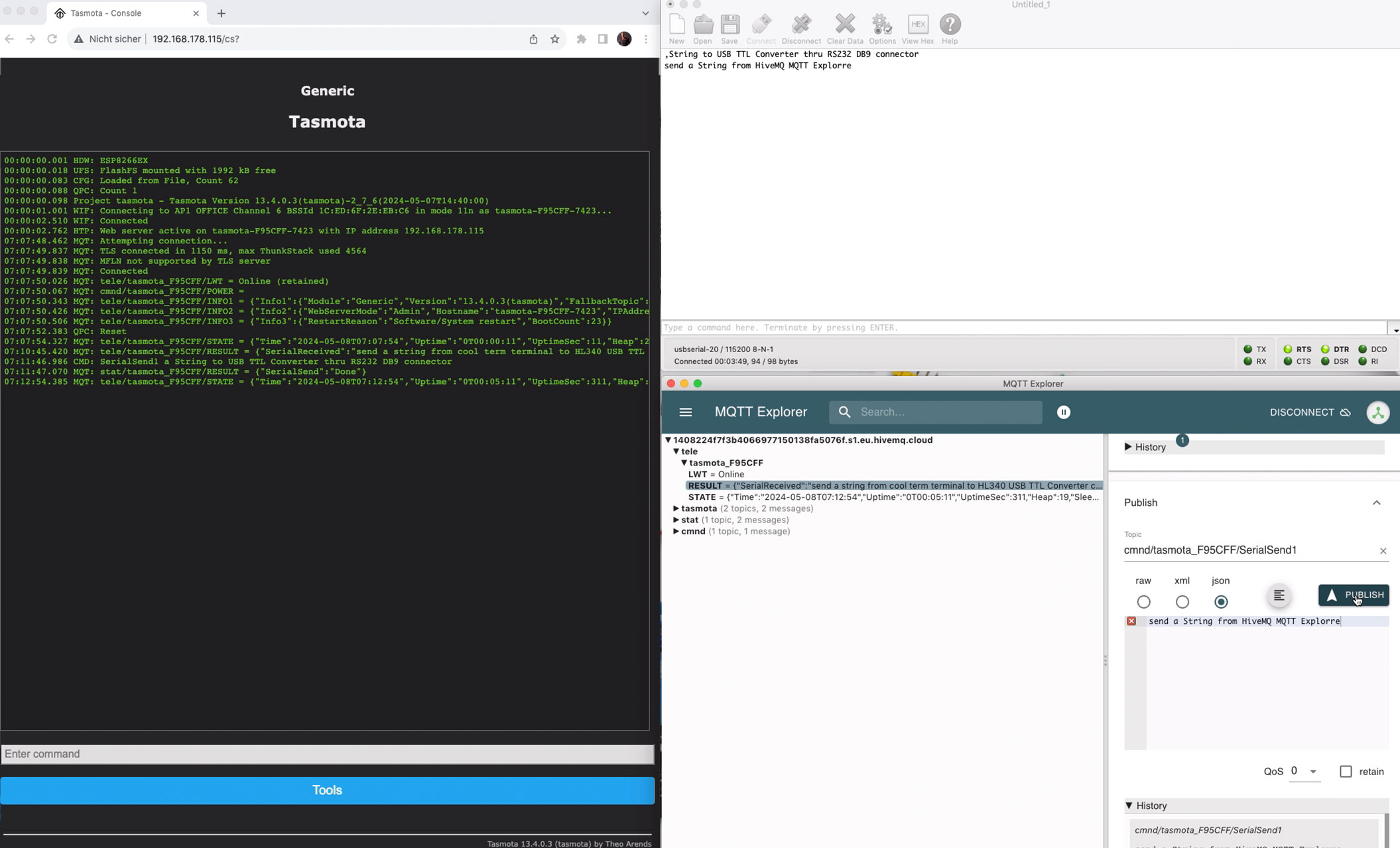 |
Tasmota MQTT subscribe
Im Eigentlichen basiert das MQTT Prinzip nunmal auf Publizieren und Abonnieren. In Anlehnung an das obige Beispiel müsste nun zunächst das Tasmota Modul eine MQTT Topic abonnieren um etwas zu empfangen.
Das Abonnieren einer Topic ist bereits mit der MQTT Konfiguration innerhalb der Tasmota Firmware erfolgt, bzw. im Detail handelt es sich um die Topic cmnd innerhalb von Tasmota. Im Detail werden sämtliche in diese Topic gesendeten Daten als Tasmota Commands abgearbeitet.
cmnd/tasmota_?????/
Wechselt man nun in den MQTT Explorer, scrollt im rechten Bereich nach unten bis der Reiter Publish erscheint kann man direkt in MQTT publizieren. Im Detail
cmnd/tasmota_?????/ gefolgt vom Tasmota Command, in unserem Beispiel SerialSend1 um einen String
|
Tasmota MQTT subscribe
Actually, the MQTT principle is based on publishing and subscribing. Based on the example above, the Tasmota module would first have to subscribe to an MQTT topic in order to receive something.
Subscribing to a topic has already been done with the MQTT configuration within the Tasmota firmware, or in detail it is the topic cmnd within Tasmota. In detail, all data sent to this topic is processed as Tasmota commands.
cmnd/tasmota_?????/
If you now switch to the MQTT Explorer, scroll down in the right area until the Publish tab appears, you can publish directly in MQTT. In detail
cmnd/tasmota_?????/ followed by the Tasmota Command, in our example SerialSend1 by a string
|