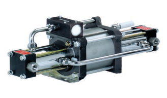
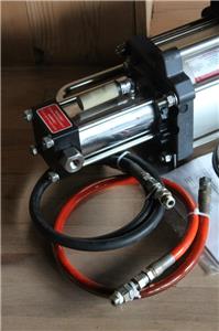
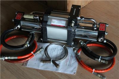
Available here is a single stage, double acting gas booster / air amplifier from Maxpro.
Model DLA 5-NN-M.
Pressure curves are shown in the photos.
Weighs 40 lbs without included hoses.
Inlet Connection: 3/8" FNPT
Outlet Connection: 3/8" FNPT
Max Temp: 140 deg F
Length: 24 inches
Width: 9 inches
Height: 9 inches
"Stall" at target pressure, automatic restart after a drop of only 1% from target pressure
PTFE seals
Unregulated pilot air port for easy restart and better control
// Ratios //
Pressure ratio 1:5
Max compression ratio 1:15
// Pressures //
Stall Pressure: 5Pa +Ps
Min inlet pressure: 2 bar (29 psi)
Max outlet pressure: 100 bar (1,450 psi)
Max drive pressure: 10 bar (145 psi)
How Does an Air Amplifier Work?
Air Amplifiers are intended for use in boosting existing plant air to higher pressures. Each amplifier has a spool valve that acts like a 4-way directional control valve. Plant air is supplied to this spool valve which automatically cycles back and forth. The plant air that is fed into the spool valve is alternately directed, as the spool cycles, to the main air drive piston in the air drive cylinder. This causes the piston to cycle back and forth in the amplifier.
There is also a high pressure section where the air, that is to be pressurized, is supplied. The air flows into the amplifier pressure chamber, through the inlet check valve(s), on the suction stroke and is pressed out of the chamber, through the outlet check valve(s), on the discharge stroke. The reciprocating movement of the air drive section, connected directly to the high pressure section, creates a positive displacement of air through the inlet and outlet check valves.
There are single and double acting models available. The single acting amplifiers displace air once per full cycle. The double acting amplifiers displace air every stroke, or twice per full cycle, providing higher and more constant flows
These amplifiers can be installed in any position, but vertical mounting is best for longest seal life.
All connections to the amplifier must be run with equal to, or greater than, the connection size in the amplifier.
How To Use Curves?
To find output flow rate from graphs below, locate desired outlet pressure on bottom axis. Move vertically from that point until you intersect the solid curve for the inlet air pressure you have available. At this point, move horizontally to the left axis. That point is the value of the outlet flow rate. To obtain the air consumption value to drive the amplifier, move vertically up from the desired outlet pressure until you intersect the dashed curve for the inlet air pressure available. From this point move horizontally to the right axis. That point is the air consumed. The total air flow required to the amplifier is the sum of the outlet flow plus the air drive flow.
Additional Notes:
The air to the amplifier should be filtered to between 5µ and 40µ and have a dew point between 0ºF and 50ºF. Very moist air can wash out the seal lubricant and very dry air may require a lubricator.
Pa = Air Drive Pressure (PSI) Ps = Supply Pressure (PSI)
Maximum air drive pressure 145 psi
Maximum operating and stall pressures must not be allowed to exceed output pressure rating.
The 9/16-18 is a 1/4" O.D. tubing, high pressure coned and threaded connection, all other connections are FNPT,
Air drive inlet connection on BPLV2 and MPLV2 is 1/4" FNPT.
Air drive inlet connection on all other air amplifiers is 1/2" FNPT.
There is a 1/8" FNPT pilot port on all amplifiers, except BPLV2 and MPLV2, that must be plumbed from air source.
We ship within 24 hours (but usually before)
If you have any questions, please do not hesitate to ask.
Maxpro DLA 5 NN-M Maximator Single Stage Double Acting Gas Booster Air Amplifier
Available here is a single stage, double acting gas booster / air amplifier from Maxpro.
Model DLA 5-NN-M. Original paperwork included.
Pressure curves are shown in the photos.
Weighs 40 lbs without included hoses.
"Stall" at target pressure, automatic restart after a drop of only 1% from target pressure
PTFE seals
Unregulated pilot air port for easy restart and better control
// Ratios //
Pressure ratio 1:5
Max compression ratio 1:15
// Pressures //
Stall Pressure: 5Pa +Ps
Min inlet pressure: 2 bar (29 psi)
Max outlet pressure: 100 bar (1,450 psi)
Max drive pressure: 10 bar (145 psi)
How Does an Air Amplifier Work?
Air Amplifiers are intended for use in boosting existing plant air to higher pressures. Each amplifier has a spool valve that acts like a 4-way directional control valve. Plant air is supplied to this spool valve which automatically cycles back and forth. The plant air that is fed into the spool valve is alternately directed, as the spool cycles, to the main air drive piston in the air drive cylinder. This causes the piston to cycle back and forth in the amplifier.
There is also a high pressure section where the air, that is to be pressurized, is supplied. The air flows into the amplifier pressure chamber, through the inlet check valve(s), on the suction stroke and is pressed out of the chamber, through the outlet check valve(s), on the discharge stroke. The reciprocating movement of the air drive section, connected directly to the high pressure section, creates a positive displacement of air through the inlet and outlet check valves.
There are single and double acting models available. The single acting amplifiers displace air once per full cycle. The double acting amplifiers displace air every stroke, or twice per full cycle, providing higher and more constant flows
These amplifiers can be installed in any position, but vertical mounting is best for longest seal life.
All connections to the amplifier must be run with equal to, or greater than, the connection size in the amplifier.
How To Use Curves?
To find output flow rate from graphs below, locate desired outlet pressure on bottom axis. Move vertically from that point until you intersect the solid curve for the inlet air pressure you have available. At this point, move horizontally to the left axis. That point is the value of the outlet flow rate. To obtain the air consumption value to drive the amplifier, move vertically up from the desired outlet pressure until you intersect the dashed curve for the inlet air pressure available. From this point move horizontally to the right axis. That point is the air consumed. The total air flow required to the amplifier is the sum of the outlet flow plus the air drive flow.
Additional Notes:
The air to the amplifier should be filtered to between 5µ and 40µ and have a dew point between 0ºF and 50ºF. Very moist air can wash out the seal lubricant and very dry air may require a lubricator.
Pa = Air Drive Pressure (PSI) Ps = Supply Pressure (PSI)
Maximum air drive pressure 145 psi
Maximum operating and stall pressures must not be allowed to exceed output pressure rating.
The 9/16-18 is a 1/4" O.D. tubing, high pressure coned and threaded connection, all other connections are FNPT,
Air drive inlet connection on BPLV2 and MPLV2 is 1/4" FNPT.
Air drive inlet connection on all other air amplifiers is 1/2" FNPT.
There is a 1/8" FNPT pilot port on all amplifiers, except BPLV2 and MPLV2, that must be plumbed from air source.
We ship within 24 hours (but usually before) If you have any questions, please do not hesitate to ask.