Tasmota ESP8266 ESP-01+ RS485 EIA-485 WLan Bridge Bausatz

RS485 WLan WiFi Bridge Tasmota Modbus EIA-485 RS-485 TCP MQTT HTTP UART Modul 5-12V

RS485 to WLan WiFi Bridge Module © ei-ot ®

RS485 to WLan WiFi Bridge Module Kit 5-12V © ei-ot ®

EI-OT ESP8266 ESP-01+ 10 Pin 32Mbit Module © ei-ot ®

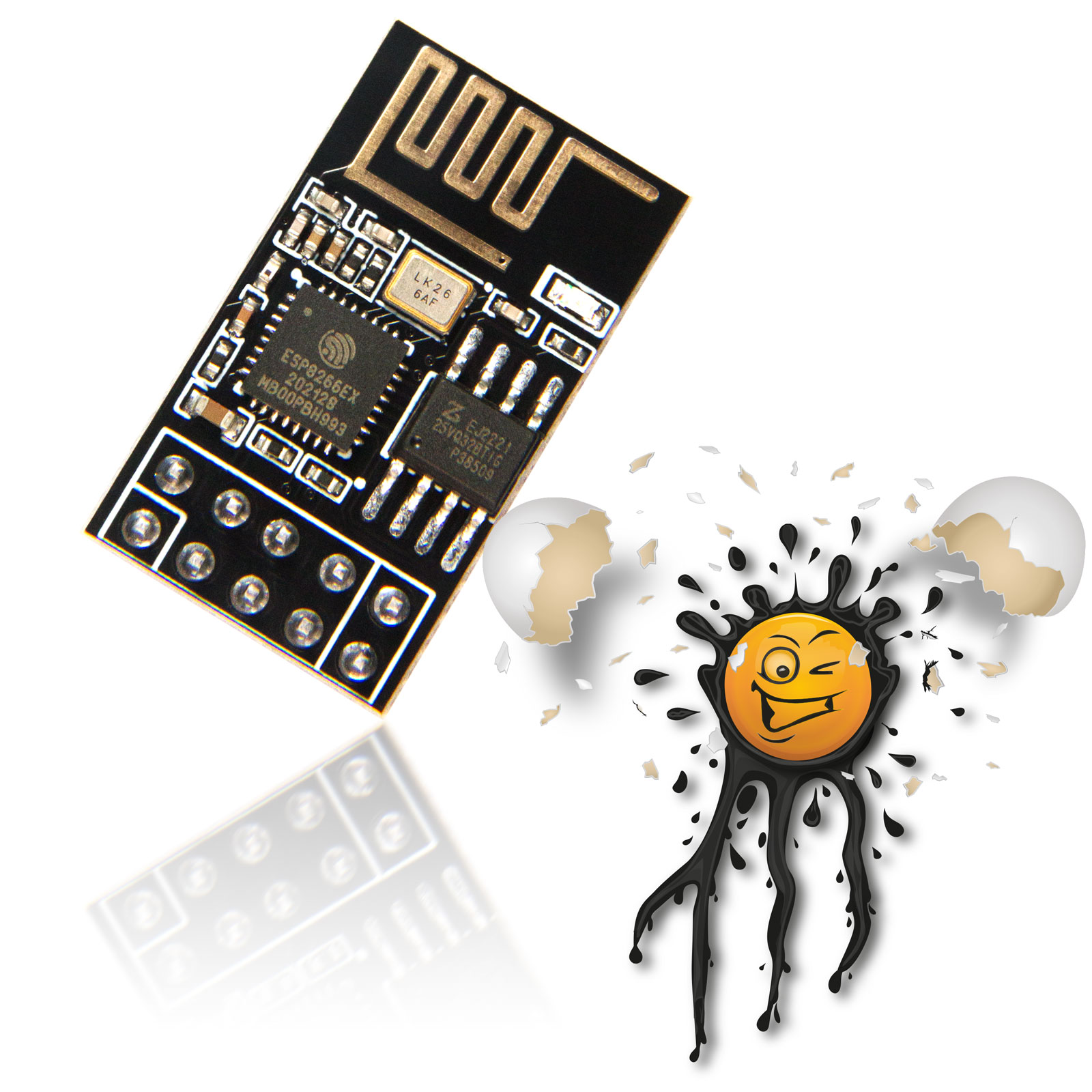
EI-OT ESP8266 ESP-01+ 10 Pin 32Mbit Module Pinout © ei-ot ®

RS485 to WLan WiFi Bridge Module Kit Assembling © ei-ot ®


RS485 to WLan WiFi Bridge Module Kit power supplyconnecting © ei-ot ®

RS485 to WLan WiFi Bridge Module Kit RS485 connection © ei-ot ®

RS485 to WLan WiFi Bridge Module Tasmota webinterface © ei-ot ®

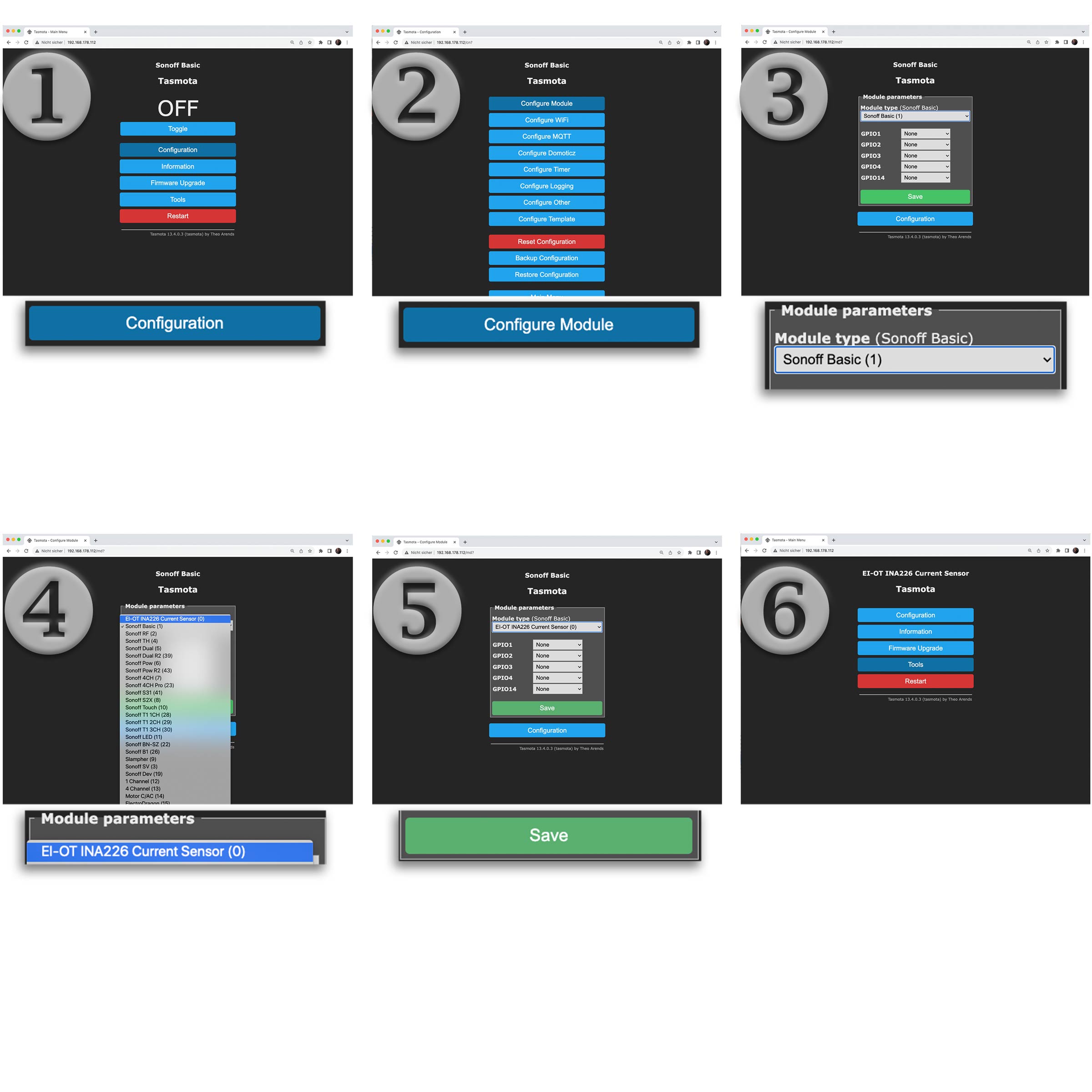
RS485 ESP8266 Module Kit PCB © ei-ot ®


RS485 to WLan WiFi Bridge Module Kit Board Dimensions © ei-ot ®

RS485 to WLan WiFi Bridge Module Kit 3D © ei-ot ®

ESP8266 ESP-01+ RS485 to WiFi Bridge Converter © ei-ot ®


Unsere EI-OT RS485 Modbus WLan Bridge Bausatz in Kombination mit unserem ESP-01+ ist bereits mit der Tasmota Firmware geflasht.

Die TasmotaFirmware ist stets in englischer Sprache und eignet sich um bei Bedarf die individuelle Firmware mittels OTA Update zu installieren, es wird kein USB TTL Konverter benötigt.

Das EI-OT RS485 Modbus WLan Bridge Modul erlaubt die einfache Umsetzung von RS485 auf Wireless Lan. Dank der Tasmota Firmware ist ein weitreichender Einsatz möglich. In der verwendeten Tasmota Firmware sind folgende Bibliotheken / Protokolle enthalten
  • Serial Bridge
  • TCP Bridge
  • Modbus Bridge
  • Eastron SDMx20 Energy Meter
  • Eastron SDM230 Energy Meter
  • Eastron SDM72 Energy Meter
  • Eastron SDM630 Energy Meter
  • Hiking DDS2382 Energy Monitor
  • Chint DDSU666 Energy Monitor
  • Solax X1 Wechselrichter
  • F&F LE-01MR Energy Monitor
  • Schneider Electric iEM3000 Energy Monitor
Inbetriebnahme

Der Einsatz des EI-OT RS485 Modbus Modul ist denkbar einfach. Die Spannungsversorgung unterstützt Eingangsspannungen von 5-12V und erfolgt zentral über die VIN Schraubklemme

  • + = VCC
  • - = GND
Die RS485 Anbindung erfolgt gleichermassen über Schraubklemme im Detail Anschluss
  • A RS485 A Kanal
  • B RS485 B Kanal
  • G RS485 GND
 
Funktionsaufbau

Das EI-OT RS485 WLan Bridge Modul basiert auf dem SP3485EN in Kombination mit dem 74HC04D zur Umsetzung des RS485 Signals auf die UART Schnittstelle des ESP-01+. Basierend auf der ESP8266 standardisierten UART Schnittstelle - GPIO1 TX, GPIO3 RX - ist das EI-OT RS485 kompatibel für jedwede ESP8266 Firmware bzw. jedwedes SDK.

Die RS485 Signalumsetzung erfolgt stets auf die UART Schnittstelle des ESP8266.

ESP8266 ESP-01+

Unser ESP-01+ Modul basiert auf der ESP8266EX MCU und verfügt über einen 32Mbit Flash Speicher, 64Kb Instruction Ram und 96Kb Data Ram. Neben dem 4 mal größeren Flash Speicher verfügt der ESP-01+ über 10 Pins und im Vergleich zum typischen ESP-01 verfügt der ESP-01+ über 5 GPIO's (sowie UART GPIO1 und GPIO3)

Je nach installierter Firmware können die GPIO's als

  • digitale Ein- oder Ausgänge
  • Schnittstelle
konfiguriert werden. Im Detail wurde der ESP-01+ im Vergleich zum ESP-01 wie folgt optimiert:
  • GPIO16 unter anderem benötigt für Deep Sleep Wake Up ersetzt den GPIO2 des Standard ESP-01
  • CH_EN wurde nicht ausgeführt und durch den GPIO12 ersetzt
  • GPIO4 und GPIO5 (oftmals für I2C verwendet) wurden auf 2 zusätzliche Pins, Pin 9 und Pin 10 ausgeführt
  • GPIO0 ist wie beim Standard ESP-01 Modul verfügbar um den Flash Modus zu aktivieren
 
Firmware
Im Auslieferungszustand ist der ESP-01+ des RS485 Modbus Moduls bereits mit Tasmota geflasht. Die Firmware wurde eigens für das EI-OT ESP8266 RS485 Modbus WLan Bridge Modul kompiliert. Neben den oben erwähnten Protokollen kann selbstredend direkt auf die serielle UART Schnittstelle des ESP8266 zugegriffen werden um RS485 Signale direkt auf
  • HTTP
  • TCP
  • MQTT
  • usw.
umzusetzen. Folgende Treiber / Sensoren sind bereits in der Tasmota Firmware enthalten: Light, WS2812, ROTARY_V1, BUZZER, ARILUX_RF, USE_SHUTTER, DEEPSLEEP, DEVICE_GROUPS, COUNTER, DS18x20,   SERIAL_BRIDGE, TCP_BRIDGE, DHT (DHT11, AM2301, DHT21, DHT22, AM2302, AM2321, SI7021), IR_REMOTE

Der Funktionsumfang des ESP-01+ Moduls wurde strikt den typischen und grundlegendem Funktionsprinzip des ESP8266EX angelehnt.

  • CH_EN Chip Enable ist bereits mit +3,3V beschaltet
  • GPIO15 verfügt über einen Pull Down Widerstand / Boot from Flash
  • GPIO00 kann bei Bedarf Low beschaltet werden / Flash Modus
Das EI-OT ESP8266 RS485 WLan Bridge Modul eignet sich somit für eigene Firmware Entwicklung als auch Firmware basierend auf
  • Espressif NonOS AT
  • Arduino
  • NodeMCU
  • MicroPython
  • Tasmota
  • ESPEasy
  • ESPurna
  • usw.
 
Das ESP8266 RS485 Modbus WLan Bridge Modul
ist bereits mit grundlegende SMD Komponenten wie
  • AMS1117-3.3 Spannungskonverter mit 2 Stück Tantal Kondensatoren
  • Kondensatoren Versorgungsspannung ESP8266EX und SP3485
  • Widerständen
  • RS485 Signal Sicherungen
  • Dioden
  • Signal Status LED RX / TX
  • Resettaster
bestückt.
 
EI-OT RS485 WLan Bridge Bausatz Lieferumfang
Neben der Hauptplatine sind im EI-OT RS485 WLan Bridge Bausatz folgende Komponenten enthalten:
  • 1 Stück ESP-01+ Modul
  • 1 Stück EI-OT RS485 WLan Bridge Platine
  • 1 Stück Pinleiste 7-polig
  • 1 Stück Schraubklemme 3-polig
  • 1 Stück Schraubklemme 2-polig
  • 1 Stück Stecksockel 2-reihig 5-polig
 

Tasmota RS485 Modbus WLan Bridge Modul

 
GPIO und weitere Anschlüsse
Bei der RS485 WLan Bridge  Platine wurde folgende Anschlüsse auf Pins (2,54mm raster) ausgeführt
  • Pinleiste 7-polig
    1. GND
    2. 3V3
    3. GPIO12
    4. GPIO16
    5. GPIO0
    6. GPIO4
    7. GPIO5

Our EI-OT RS485 Modbus WiFi Bridge Kit in combination with  ESP-01+ Module with Tasmota Firmware.

The Tasmota firmware is always in English and is suitable for installing the individual firmware using OTA update function, - no USB TTL converter is required - Thanks to the Tasmota firmware, extensive use is possible. The following libraries/protocols are included in the Tasmota firmware
  • Serial Bridge
  • TCP Bridge
  • Modbus Bridge
  • Eastron SDMx20 Energy Meter
  • Eastron SDM230 Energy Meter
  • Eastron SDM72 Energy Meter
  • Eastron SDM630 Energy Meter
  • Hiking DDS2382 Energy Monitor
  • Chint DDSU666 Energy Monitor
  • Solax X1 Wechselrichter
  • F&F LE-01MR Energy Monitor
  • Schneider Electric iEM3000 Energy Monitor
 
Application

Using the EI-OT RS485 Modbus WiFi Bridge module is extremely easy. The power supply supports input voltages of 5-12V and is carried out centrally via the VIN screw terminal

  • + = VCC
  • - = GND
The RS485 connection is also made via a screw terminal in the detailed connection
  • A RS485 A Kanal
  • B RS485 B Kanal
  • G RS485 GND
 

Working Principle
The EI-OT RS485 WiFi Bridge Module is based on the SP3485EN in combination with the 74HC04D to convert the RS485 signal to the UART interface of the ESP-01+. Based on the ESP8266 standardized UART interface - GPIO1 TX, GPIO3 RX - the EI-OT RS485 to WiFi Bridge Module is compatible with any ESP8266 firmware or any SDK. The RS485 signal conversion always takes place on the UART interface of the ESP8266.

ESP8266 ESP-01+
The ESP-01+ Module is based on the ESP8266EX MCU and features 32Mbit Flash memory, 64Kb Instruction Ram and 96Kb Data Ram. Compared to typical ESP-01 Modules the ESP-01+ Module has 10 Pins and supports 5 GPIO (+ UART GPIO1 and GPIO3) Depending on the installed firmware, the GPIO's can be used as
  • digital inputs or outputs
  • interface like
In Detail the ESP-01+ GPIO's:
  • GPIO2 Pin is replaced thru GPIO16 (used for deep sleep wake up)
  • CH_EN Pin is replaced thru GPIO12
  • GPIO4 and GPIO5 (often used for I2C) connected to 2 additional Pins (Pin9 and Pin10)
  • same GPIO0 function / position as ESP-01 Standard Module to select boot or flash mode
 
Firmware
The ESP-01+ comes already flashed with Tasmota Firmware. The firmware was compiled specifically for the EI-OT RS485 Modbus WiFi Bridge module. In addition to the protocols mentioned above, the serial UART interface of the ESP8266 can of course be accessed directly to receive and send RS485 signals or extended to protocols such as
  • HTTP
  • TCP
  • MQTT
  • ...
The following drivers / sensors are already included in the Tasmota firmware: Light, WS2812, ROTARY_V1, BUZZER, ARILUX_RF, USE_SHUTTER, DEEPSLEEP, DEVICE_GROUPS, COUNTER, DS18x20,   SERIAL_BRIDGE, TCP_BRIDGE, DHT (DHT11, AM2301, DHT21, DHT22, AM2302, AM2321, SI7021), IR_REMOTE The range of functions of the EI-OT ESP-01+ current sensor module was strictly based on the typical and basic functional principle of the ESP8266EX.
  • CH_EN Chip Enable is already connected to +3.3V
  • GPIO15 has a pull down resistor / boot from flash
  • GPIO00 can be wired low if required / flash mode
The EI-OT ESP8266 current sensor module is therefore suitable for your own firmware development as well as firmware based on
  • Espressif NonOS AT
  • Arduino
  • NodeMCU
  • MicroPython
  • tasmota
  • ESPEasy
  • ESPurna
  • etc.
 
The ESP8266 INA226 Current Sensor Module
is already assembled with SMD components
  • AMS1117-3.3 voltage converter in combination with 2 pcs. Tantal capacitors
  • capacitors
  • resistors
  • RS485 Level Signal Fuses
  • Diodes
  • Signal Status LED RX / TX
  • Reset Button
 
The EI-OT RS485 WiFi Bridge Kit scope of delivery
In addition to the main board, the following components are included in the EI-OT RS485 WiFi Bridge board kit :
  • 1 pcs. ESP-01+ Module
  • 1 pcs. EI-OT RS485 WiFi Bridge PCB
  • 1 pcs. Pinheader 1-row 7-pole
  • 1 pcs. Screw Terminal 3-pole
  • 1 pcs. Pin Socket 2-rows 5-pole
 

Tasmota RS485 Modbus WiFi Bridge Module

 
GPIO and additionally Connections
The ESP8266 developer board has the following connections on pins (2.54mm pitch).
  • Pin Header 7-pole
    1. GND
    2. 3V3
    3. GPIO12
    4. GPIO16
    5. GPIO0
    6. GPIO4
    7. GPIO5
EI-OT Tasmota ESP8266 RS485 Modbus WiFi Board Features
VCC Spannungsversorgung DC 5-12V  VCC  / Input Voltage DC 5-12V
Schnittstellen

je nach GPIO Konfiguration

Interfaces based on GPIO configuration
Protokolle HTTP, REST, MQTT, Domoticz, Home Assistant Protocols HTTP, REST, MQTT, Domoticz, Home Assistant
typische Anwendung RS485 Modbus auf Wireless Lan Brdige typical Application  RS485 Modbus to WiFi Bridge
Leistung Strom Power Current
AMS1117-3.3 Ausgangsstrom 800mA (max.) AMS1117-3.3 Output Current 800mA (max.)
Stromverbrauch (ohne LED und externe Sensoren) 70mA (durchschnittlich)

250mA (max.)
23mA (Modem Sleep)
5mA (Light Sleep)
<3µA (Deep Sleep)

Current Consumption (w/o LED and external sensors) 70mA (average)

250mA (max.)
23mA (Modem Sleep)
5mA (Light Sleep)
<3µA (Deep Sleep)

WLan 802.11 WiFi 802.11
Frequenzbereich 2412 – 2884 Mhz. Frequency Range 2412 – 2884 Mhz.
Sendeleistung 802.11b: 16±2 dBm (@11Mbps)
802.11g: 14±2 dBm (@54Mbps)
802.11n: 13±2 dBm (@HT20, MCS7)
Transmit Power 802.11b: 16±2 dBm (@11Mbps)
802.11g: 14±2 dBm (@54Mbps)
802.11n: 13±2 dBm (@HT20, MCS7
Empfangs – Empfindlichkeit CCK, 1 Mbps : -90dBm
CCK, 11 Mbps: -85dBm
6 Mbps (1/2 BPSK): -88dBm
54 Mbps (3/4 64-QAM): -70dBm
HT20, MCS7 (65 Mbps, 72.2 Mbps): -67dBm
Receiving Sensitivity CCK, 1 Mbps : -90dBm
CCK, 11 Mbps: -85dBm
6 Mbps (1/2 BPSK): -88dBm
54 Mbps (3/4 64-QAM): -70dBm
HT20, MCS7 (65 Mbps, 72.2 Mbps): -67dBm
Sicherheit WEP/WPA-PSK/WPA2-PSK Security WEP/WPA-PSK/WPA2-PSK
Antenne integrierte PCB Antenne 2 dBi (ESP-01+) Antenna integrated 2dBi PCB Antenna (ESP-01+)
IPv4 Unterstützung DHCP und statisch IPv4 Support DHCP and static
Anschlüsse Connections
VIN  Schraubklemme 2-polig VIN+ 5-12V Spannungsversorgung Vin Screw Terminal 2-pole VIN+ 5-12V Power Supply
RS485 Schraubklemme 3-polig B
A
GND
RS485 Screw Terminal 3-pole B
A
GND
Pinleiste 7-polig GND
3V3
GPIO12
GPIO16
GPIO0
GPIO4
GPIO5
Pinheader 7-pole GND
3V3
GPIO12
GPIO16
GPIO0
GPIO4
GPIO5
EI-OT RS485 WiFi Bridge Module Board assembling
EI-OT RS485 WLan Bridge Modul bestücken

Das EI-OT Tasmota RS485 WLan Bridge Modul ist bereits mit SMD Komponenten wie

  • AMS1117 3,3V Spannungskonverter nebst Kondensatoren
  • Widerständen
  • SP3485EN RS485 UART Konverter
  • 74HC04D Inverter IC
  • Reset Taster
  • SMD Sicherungen
  • Dioden
  • LED's
bestückt.

Zur Inbetriebnahme müssen lediglich, nachfolgende Komponenten wie in nebenstehender Grafik dargestellt bestückt / verlötet werden.

Die Bestückung des RS485 WLan Bridge Moduls Schritt für Schritt:
  1. Platziere den 2x5 Pin Stecksockel auf H1 und verlöte die Pins auf der Rückseite
  2. Platziere die 7-polige Pinleiste auf H2 und verlöte die Pins auf der Rückseite
  3. Platziere die 2-polige Schraubklemme auf VCC und verlöte die Pins auf der Rückseite
  4. Platziere die 3-polige Schraubklemme auf RS485 und verlöte die Pins auf der Rückseite
Das RS485 WLan Bridge Modul ist fertig bestückt.
EI-OT RS485 WiFi Bridge Module assembling

The EI-OT RS485 WiFi Bridge Module is already equipped with SMD components such as

  • AMS1117 3.3V Voltage Converter and capacitors
  • Resistors
  • SP3485EN RS485 UART Converter
  • 74HC04D Inverter IC
  • Reset Button
  • SMD Fuses
  • Diodes
  • LED's
For completion, the following components simply need to be assembled. The assembly of the EI-OT RS485 WiFi Bridge Module step by step:
  1. Place the 2x5 pin socket on H1 and solder the pins on the bottom side
  2. Place the 7-pin header on H2 and solder the pins on the bottom side
  3. Place the 2-pin  screw terminal on VCC and solder the pins on the bottom side
  4. Place the 3-pin  screw terminal on RS485 and solder the pins on the bottom side
The basic assembling of the RS485 WiFi Bridge Module is finished.
EI-OT RS485 WiFi Bridge Module 5-12V Module connection
Spannungsversorgung

Die  Spannungsversorgung des RS485 WiFi Bridge Modul erfolgt  über die 2-polige Schraubklemme

  • + Anschlussklemme 5 bis 12V +
  • - Anschlussklemme 5 bis 12V -
Zur Spannungsversorgung eignet sich sowohl ein typisches Steckernetzteil als auch jedwede Gleichspannung im Bereich von 5-12V mit 200mA.
Power Supply
The RS485 WiFi Bridge module is supplied with power via the 2-pin screw terminal
  • + Connection terminal 5 to 12V +
  • - Connection terminal 5 to 12V -
Both a typical plug-in power supply and any DC voltage in the range of 5-12V with 200mA are suitable for power supply.
EI-OT ESP-01+ ESP8266 RS485 Module connection
RS485 Anschluss

Die RS485 Bus Anbindung erfolgt über die 3-polige Schraubklemme

  • G Klemme zum Anschluss an GND des RS485 Bus Teilnehmer (optional)
  • A Klemme zum Anschluss an A Signal des RS485 Bus Teilnehmer
  • B Klemme zum Anschluss an B Signal des RS485 Bus Teilnehmer
RS485 Connection
The RS485 bus connection is made via the 3-pin screw terminal
  • G terminal for connection to GND of the RS485 bus participant (optional)
  • A terminal for connecting to A signal of the RS485 bus participant
  • B terminal for connection to B signal of the RS485 bus participant
Tasmota WLan WiFi Konfiguration in 5 Schritten
Tasmota WLan Konfiguration

Die Tasmota Firmware erlaubt eine einfache WLan Konfiguration mittels Webinterface. An dieser Stelle sei erwähnt, die Tasmota Firmware unterstützt den SoftAP Modus (Access Point) lediglich zur WLan Konfiguration. Sobald das jeweilige Modul als Client in einem bestehenden Netzwerk eingebunden wurde, wird der SoftAP Modus nicht mehr unterstützt.

Tasmota Client Anbindung mittels Webinterface

Nachdem das jeweilige Modul mit Spannung versorgt wurde startet das Modul im SoftAP Modus. Innerhalb der Netzwerkumgebung eines

  • Computers
  • Mobiltelefon
  • Tablet
erscheint nun ein neuer Tasmota SoftAP / Access Point.

Die WLan Konfiguration mittels dem Tasmota Webinterface erfolgt mittels 5 einfachen Schritten:

  1. Stelle eine WLan Verbindung über Systemeinstellungen / Netzwerkeinstellungen zu dem Tasmota Soft AP wird als tasmota-??????-???? Access Point angezeigt. Der Tasmota SoftAP verfügt über keine Sicherheitseinstellungen, es wird kein Passwort benötigt.
  2. Nachdem eine WLan Verbindung hergestellt wurde öffnet sich üblicherweise das Tasmota Webinterface innerhalb des festgelegten Standardbrowsers. Alternativ kann das Tasmota Webinterface durch Aufruft der url http://192.168.4.1 innerhalb eines Webbrowsers aufgerufen werden. Tasmota führt eigenständig einen Netzwerkscan aus und gibt die Liste verfügbarer Netzwerke aus. Sollte das gewünschte Netzwerk nicht im Tasmota Webinterinterface nicht aufgelistet sein, Scan for all WiFi Networks anklicken, sodass erneut ein Netzwerkscan durchgeführt wird.
  3. Wähle das jeweilige Netzwerk aus (anklicken), Tasmota übernimmt dann das jeweilige Netzwerk in das Textfeld WiFi Network. Ergänze nun die erforderlichen Parameter durch das Netzwerk Passwort und klicke auf den Button Save.
  4. Das Tasmota Modul startet eigenständig und versucht eine Verbindung mit dem zuvor festgelegtem Netzwerk herzustellen (Dauer ca. 20-30 Sekunden).
  5. Wurde die Verbindung erfolgreich hergestellt erscheint die Meldung Successful WiFi Connection sowie die Angabe der vom Router mittels DHCP zugewiesenen IP Adresse.
    1. Wichtig das Tasmota Modul ist nun nur noch über dieses IP Adresse erreichbar.
    2. Bitte WLan Verbindung überprüfen, ob sich der Client im gleichen Netzwerk wie das Tasmota Modul befindet (gegebenenfalls mit dem entsprechenden WLan Netzwerk verbinden) , da sonst kein Redirect erfolgen kann.
  6. Das Tasmota Modul ist nun als WLan Client unter der zuvor (unter 5.) ausgegebenen IP Adresse erreichbar.
Tasmota WiFi Configuration

The Tasmota firmware allows simple WiFi configuration thru Browser web interface. At this point it should be mentioned that the Tasmota firmware only supports SoftAP mode (access point) for WiFi configuration. As soon as a Tasmota module has been integrated as a WiFi client in an existing network, SoftAP mode is disabled.

Tasmota WiFi Client Setup
After Tasmota module has been supplied with voltage, the module starts as Tasmota SoftAP. Within network environment of
  • Computer
  • Mobile phone
  • Tablet
a new Tasmota SoftAP / Access Point appears. The WiFi configuration using the Tasmota web interface in 5 simple steps:
  1. Establish a WiFi connection via system settings / network settings to the Tasmota Soft AP, appears as tasmota-??????-???? access point. The Tasmota SoftAP has no security settings, so no password is required.
  2. After a WiFi connection has been established, the Tasmota web interface usually opens within the specified standard browser. Alternatively, the Tasmota web interface can be accessed by accessing the url http://192.168.4.1 within a web browser. Tasmota independently runs a network scan and outputs the list of available networks. If the desired network is not listed click on Scan for all WiFi Networks so that a network scan is carried out again.
  3. Select the respective WiFi network (click), Tasmota will then add the respective network to the WiFi Network text field. Now add the network password to the required parameters and click on the Save button.
  4. The Tasmota module starts independently and tries to establish a connection to the previously defined network (duration approx. 20-30 seconds).
  5. If the connection has been established successfully, the message Successful WiFi Connection appears as well as the IP address of the Tasmota Module assigned by the router using DHCP.
    1. Important: the Tasmota module can now only be reached via this IP address.
    2. Please make sure the WiFi connection to  your client is in the same network as the Tasmota module. If necessary, connect to the corresponding WiFi network, otherwise no redirect can proceeded.
  6. The Tasmota module can now be reached as a WiFi client thru the IP address previously issued (under 5.).
Behebung etwaiger Probleme

Sollte man die IP Adresse vergessen haben, kann diese üblicherweise im Webinterface des Routers unter Netzwerk oder WLan gefunden werden.

Bei falschen WLan / Netzwerk Parametern, z.B. falschem Passwort wird die Verbindung seitens des Routers abgewiesen. Dementsprechend muss das Tasmota Modul mittels Factory Default Reset wie folgt zurückgesetzt werden
  • das Modul 6 mal für 1-2 Sekunden mit Spannung versorgen, beim 7 mal die Spannungsversorgung bestehen lassen, das Tasmota Modul startet dann eigenständig im SoftAP Modus, sodass erneut wie oben beschrieben die Konfiguration durchgeführt werden kann. Bitte beachten bei Steckernetzteilen bleibt die Spannungsversorgung oftmals über mehrer Sekunden bestehen, d.h. die Pausen zwischen der erneuten Spannungsversorgung sollten einige Sekunden (5-10 Sekunden) betragen.
Troubleshooting

In case of IP address was lost it can usually be found in the router's web interface under Network or WiFi.

In case of WiFi / network parameters are incorrect, e.g. an incorrect SSID Name or password, the connection will be rejected by the router. Accordingly, the Tasmota module must be reset using a factory default reset as follows
  • Supply the module with power 6 times for 1-2 seconds. On seventh time, leave the power supply on. The Tasmota module then starts independently in SoftAP mode so that the configuration can be carried out again as described above. Please note that with plug-in power supplies, the voltage supply often remains for several seconds, i.e. the breaks between the renewed voltage supply should be a few seconds (5-10 seconds).
EI-OT ESP-01+ ESP8266 RS485 WiFi Bridge Module GPIO's
Tasmota Konfiguration

Der grundlegende Aufbau des RS485 WiFi Bridge Modul basiert auf dem SP3485EN in Kombination mit dem 74HC04.

Im Detail wird dabei lediglich das RS485 Signal, bzw. der RS485 Level auf den UART Level des ESP8266 umgesetzt. Dabei wurde
  • GPIO1 TXD
  • GPIO3 RXD
gemäß der standardmässigen Konfiguration des ESP8266 verwendet, diesbezüglich ist im Eigentlichen keine weitere Konfiguration notwendig. Neben GPIO1 und GPIO3 verfügt das EI-OT RS485 WiFi Bridge Modul über folgende auf die 7-polige Pinleiste ausgeführte GPIO's
  • GPIO0 (eingeschränkt nutzbar / Low Level = Flash Modus)
  • GPIO4 (individuell nutzbar)
  • GPIO5 (individuell nutzbar)
  • GPIO16 (individuell nutzbar)
Tasmota Configuration
The basic structure of the RS485 WiFi Bridge Module is based on the SP3485EN in combination with the 74HC04. In detail, just the RS485 signal or lets say the RS485 level is converted to the UART level of the ESP8266 serial interface. This was done
  • GPIO1 TXD
  • GPIO3 RXD
used according to the standard configuration of the ESP8266, no further configuration is actually necessary in this regard. In addition to GPIO1 and GPIO3, the EI-OT RS485 WiFi Bridge module has the following GPIOs on the 7-pin pin strip
  • GPIO0 (limited use / low level = flash mode)
  • GPIO4 (can be used individually)
  • GPIO5 (can be used individually)
  • GPIO16 (can be used individually)
 
Modbus Konfiguration

Modbus ist ein typische Kommunikationsprotokoll zwischen Master und Slaves basierend auf

  • Modbus / RTU
  • Modbus / ASCII
  • Modbus / TCP
Die Tasmota Firmware verfügt über eine Vielzahl an integrierten Modbus Protokollen basierend auf Endgeräten bzw. Standards, zur Aktivierung muß GPIO1 TX und GPIO3 RX entsprechend konfiguriert werden.
  • Modbus Bridge
    • GPIO1 ModBr TX
    • GPIO3 ModBr RX
  • Eastron SDMx20 Energy Meter
    • GPIO1 SDMx20 TX
    • GPIO3 SDMx20 RX
  • Eastron SDM230 Energy Meter
    • GPIO1 SDM230 TX
    • GPIO3 SDM230 RX
  • Eastron SDM72 Energy Meter
    • GPIO1 SDM72 TX
    • GPIO3 SDM72 RX
  • Eastron SDM630 Energy Meter
    • GPIO1 SDM630 TX
    • GPIO3 SDM630 RX
  • Hiking DDS2382 Energy Monitor
    • GPIO1 DDS238-2 TX
    • GPIO3 DDS238-2 RX
  • Chint DDSU666 Energy Monitor
    • GPIO1 DDSU666 TX
    • GPIO3 DDSU666 RX
  • Solax X1 Wechselrichter
    • GPIO1 SolaxX1 TX
    • GPIO3 SolaxX1 RX
  • F&F LE-01MR Energy Monitor
    • GPIO1 LE-01MR TX
    • GPIO3 LE-01MR RX
  • Schneider Electric iEM3000 Energy Monitor
    • GPIO1 iEM3000 TX
    • GPIO3 iEM3000 RX
Aufgrund abweichender Geräteversion und / oder Firmware Version Änderungen können Änderungen im jeweiligen Protokoll vorliegen, hier sei auf die jeweilige Tasmota- bzw. Hersteller- Dokumentation verwiesen.
Modbus Configuration
Modbus is a typical communication protocol based on master and slaves
  • Modbus/RTU
  • Modbus/ASCII
  • Modbus/TCP
The Tasmota firmware has a variety of integrated Modbus protocols based on end devices or standards; for activation, GPIO1 TX and GPIO3 RX must be configured accordingly
  • Modbus Bridge
    • GPIO1 ModBr TX
    • GPIO3 ModBr RX
  • Eastron SDMx20 Energy Meter
    • GPIO1 SDMx20 TX
    • GPIO3 SDMx20 RX
  • Eastron SDM230 Energy Meter
    • GPIO1 SDM230 TX
    • GPIO3 SDM230 RX
  • Eastron SDM72 Energy Meter
    • GPIO1 SDM72 TX
    • GPIO3 SDM72 RX
  • Eastron SDM630 Energy Meter
    • GPIO1 SDM630 TX
    • GPIO3 SDM630 RX
  • Hiking DDS2382 Energy Monitor
    • GPIO1 DDS238-2 TX
    • GPIO3 DDS238-2 RX
  • Chint DDSU666 Energy Monitor
    • GPIO1 DDSU666 TX
    • GPIO3 DDSU666 RX
  • Solax X1 Wechselrichter
    • GPIO1 SolaxX1 TX
    • GPIO3 SolaxX1 RX
  • F&F LE-01MR Energy Monitor
    • GPIO1 LE-01MR TX
    • GPIO3 LE-01MR RX
  • Schneider Electric iEM3000 Energy Monitor
    • GPIO1 iEM3000 TX
    • GPIO3 iEM3000 RX
Due to different device and/or firmware versions, there may be changes in the respective protocol; please refer to the respective Tasmota or manufacturer documentation.
 
serielle Kommunikation
Zwar unterstützt die Tasmota Firmware eine Vielzahl von RS485 basierenden Protokollen, reduziert auf die Hardware erfolgt aber stets eine Umsetzung des RS485 Level auf die serielle UART Schnittstelle des ESP8266. Dementsprechend kann eine direkte Kommunikation, beispielsweise über die Tasmota Console erfolgen. Im folgenden RS485 WLan Bridge  Beispiel wird ein typischer USB RS485 Konverter direkt mit dem EI-OT RS485 verbunden:
  • A Kanal auf A Kanal
  • B Kanal auf B Kanal
Im Bezug des PC / MAC wird ferner ein typisches serial terminal Programm (Roger Meiers Cool Term) verwendet. Im eigentlichen Bedarf es keiner großen Einstellungen, lediglich die Baudrate des seriellen Terminals muß auf 115200 b/s (Tasmota Firmware Standard Baudrate) gesetzt werden. Ferner sollte der Line Modus (Befehlszeilen Modus) im Terminal Programm aktiviert sein.
serial Communication
Although the Tasmota firmware supports a variety of RS485-based protocols. But reduced to the hardware / basic function, the RS485 level is always converted to 3.3V UART level transmitted thru serial UART interface of the ESP8266. Accordingly, direct communication can take place, for example via the Tasmota Console. In the following RS485 WiFi Bridge example, a typical USB RS485 converter is connected directly to the EI-OT RS485:
  • A channel on A channel
  • B channel to B channel
A typical serial terminal program (Roger Meier's Cool Term) is also used for the PC / MAC. In actual fact, no major settings are required, only the baud rate of the serial terminal must be set to 115200 b/s (Tasmota firmware standard baud rate).
EI-OT ESP8266 RS232 RX TX serial Bridge Configuration
RS485 WLan Beispiel
Nachdem wie oben beschrieben eine entsprechende Verbindung zwischen RS485 USB Konverter und dem RS485 WLan Bridge Modul hergestellt wurde, kann auch schon mit direkten WLan RS485 Kommunikation begonnen werden.
  1. klicke auf Tools um das Tasmota Tools Menü zu öffnen
  2. klicke im Tasmota Tools Menü auf Console
  3. im jeweiligen seriellen Terminal Programm sollte die Verbindung zum USB RS485 Konverter entsprechend geöffnet sein. Tippt man nun in der Befehlszeile der Tasmota Console SerialSend just a String from Tasmota over Wifi to RS485 USB Converter ein und drückt die Taste ENTER
  4. erscheint der vorgenannte String auch schon im seriellen Terminal Programm
  5. Wechselt man nun in die Befehlszeile des seriellen Terminal Programms und gibt hier back to Tasmota thru USB RS485 Converter ein und drückt die Taste ENTER
  6. so erscheint der vorgenannte Text im Ausgabefenster der Tasmota Console
In Anlehnung an die Tasmota Firmware, im Detail serial commands sowie in Kombination mit Tasmota Rules kann jedwede individuelle Lösung zur Herstellung einer individuellen RS485 WLan Bridge herbeigeführt werden.
RS485 WiFi Example
After a connection  between the RS485 USB converter and the RS485 WLan bridge module has been established (as described above), a WiFi RS485 WiFi brdige communication can begin.
  1. click on Tools to open the Tasmota Tools menu
  2. click Console in the Tasmota Tools menu
  3. The connection to the USB RS485 converter should be open accordingly in the respective serial terminal program. Now type in the command line of the Tasmota Console SerialSend just a String from Tasmota over Wifi to RS485 USB Converter and press the ENTER key
  4. the string now appears in the serial terminal program
  5. now switch to the command line of the serial terminal program and write  back to Tasmota thru USB RS485 Converter into command line and press the ENTER key
  6. and the string appears in the output window of the Tasmota Console
Based on the Tasmota firmware, in detail serial commands and / or in combination with Tasmota Rules, any solution can be created to create an individual RS485 WLan bridge.