Tips:
(1) The module interface of our shop is clear and the performance is stable. Please perform functional verification under the corresponding experimental conditions in conjunction with the schematic diagram provided by our shop.
(2) The basic parameters of this module are in the details page, providing PDF information of the module information, source code of the routine, and no engineering files. Please inform the buyer, if you have any operation problems, you can consult customer service.
(3) Buyers, before using the module, please read the details page of this module to understand the power supply and use restrictions, to avoid damage to the module due to improper operation.
(4) The modules of our shop are guaranteed to provide real module parameters, functions and pictures, and all modules are tested and shipped.
Please contact customer service after purchase, we will send the module information to your mailbox.
Module parameters:
Module model: AD7606
Module type: analog-to-digital conversion module
Module power supply: DC5V
Module current: 20mA (MAX)
Module communication protocol: SPI serial, 8-channel data parallel
Module provides routines: STM32F103RBT6; SPI serial (additional F407 platform parallel routine)
Routine platform: STM32F103X-M3; KEIL5 version source code
Module control signal level: 3.3V
Module input voltage range: ± 5V or ± 10V; software switch range
Input impedance: 1M ohm
ADC resolution digits: 16
Sampling rate: 200KSPS; all channels
Number of input channels: 8 channels independent; simultaneous sampling
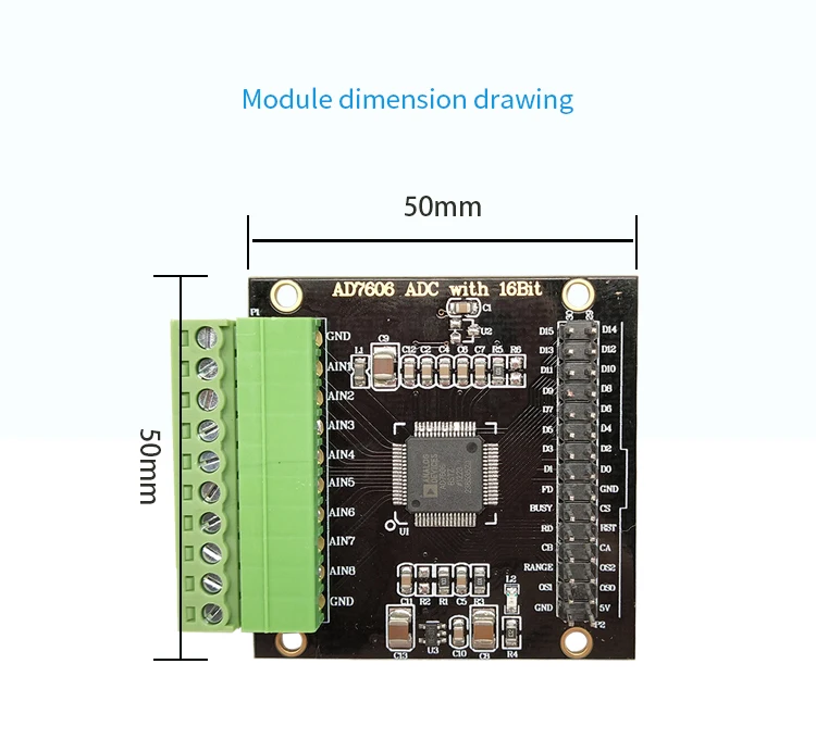
Module input interface: 3.81-8PIN terminal
Reference voltage: internal 2.5V; external input reference for solderable SOT-23 package
Oversampling mode: 6; 2 times, 4 times, 8 times, 16 times, 32 times, 64 times
Output mode: 8-channel data serial or parallel; the default welding R1 is serial mode. Welding R2 is in parallel mode.
Module features: multiple; analog input clamp protection, second-order anti-aliasing filter, track-and-hold amplifier, digital filter
Module applications: multiple; power line monitoring and protection, multi-phase motor control, instrumentation and control, multi-axis positioning, data acquisition and other systems
Module interface type: 3.81-10PIN socket, XH2.54 double-row pin data interface
Module description:
The AD7606 is a 16-bit, 8-channel synchronous sampling, analog-to-digital data acquisition chip with a sampling rate of up to 200 kSPS per channel, built-in analog input clamp protection, second-order anti-aliasing filter, track-and-hold amplifier, 16-bit charge redistribution successive approximation ADC, digital filter, 2.5V reference voltage source, reference voltage buffer, and high-speed serial and parallel interfaces. 5V single power supply, with on-chip filtering and high input impedance, so there is no need to drive the operational amplifier and external bipolar power supply; the anti-aliasing filter has a 3 dB cut-off frequency of 22 kHz; when the sampling rate is 200 kSPS, it has 40 dB anti-aliasing suppression characteristics; input clamp protection circuit to ensure input withstand voltage of ± 16.5V. It can be used in power line monitoring and protection, multi-phase motor control, instrumentation and control, multi-axis positioning, data acquisition and other systems.
Note: The chip features are only for user selection reference. Non-modules have this feature.

Precautions for using the module:
(1) The module is a low-power module, the power supply does not exceed 5.5V, and the signal input voltage cannot exceed ± 16.5V.
(2) Since the module is a high-precision device, in order to avoid unnecessary interference, it is recommended to use a linear power supply.
(3) It is recommended that the output signal line be as short as possible. If the line is too long, it is easy to introduce noise signals. Poor contact or poor quality wires may cause signal attenuation or excessive noise.
(4) The delivered code is only used for the supporting main control board. No single-chip microcomputer tutorial is provided. Functions other than product details display need to be developed by yourself.
(5) If you need to simply test the function of the module, it is recommended to use it with our store's control board. After correct wiring, power supply to the control board can realize signal acquisition and display.
Frequently asked questions:
Q: How much sampling rate can AD7606 serial data reach?
A: Theoretically, 8-channel 200K serial data output can be achieved, but the general single-chip microcomputer can not achieve 200KSPS with serial data, because the main frequency and IO speed of the single-chip microcomputer are not enough.
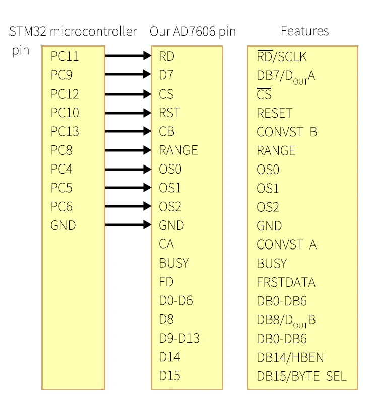
Q: Is there any problem if the CA and CB pins on the back of the board are shorted together?
A: According to the schematic diagram, CA and CB are connected together through the jump point, which is normal.
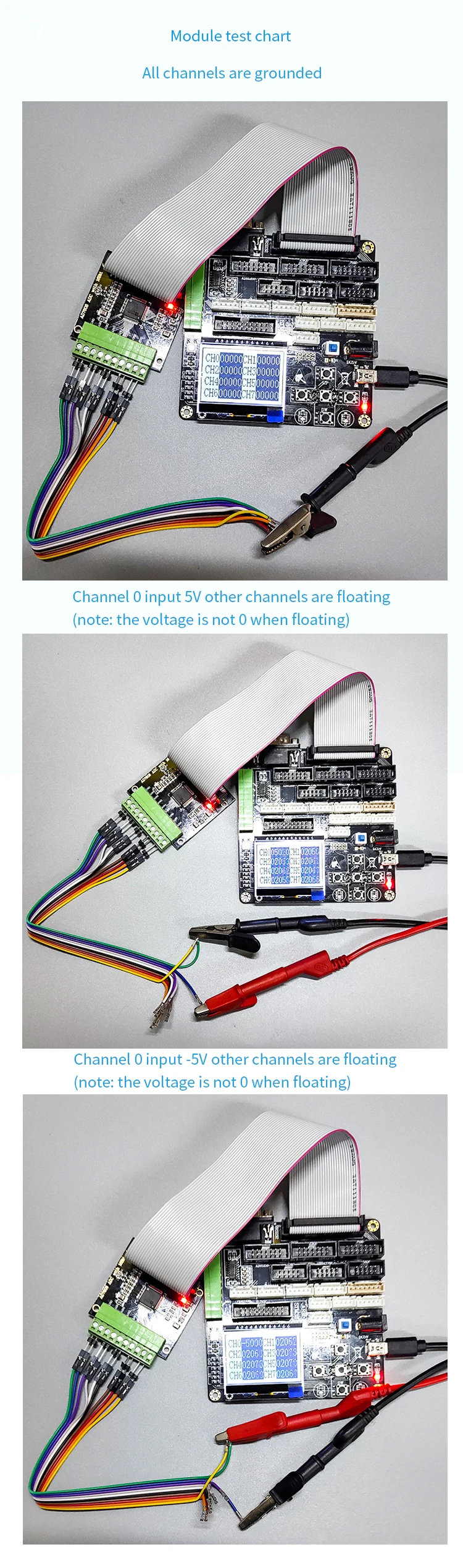
Q: After the module is driven normally, the pins that are not connected to voltage show that there is voltage, is it normal?
A: The module collects 8 channels at the same time by default. When no voltage is connected, the floating voltage on the pin is also collected. The pin can be directly grounded, which is 0 voltage.
Q: Is the maximum value 65535? How is this data converted?
A: The most significant bit of AD7606 is the sign bit. When the range is ± 5V, 0 ~ 32767 corresponds to 0V ~ 5V, 32768 ~ 65535 corresponds to -5V ~ 0V, 32768 ~ 65535 is a 16-bit unsigned integer, actually equal to -32767 ~ 0 of 16-bit signed number. Similarly, plus or minus 10V is also converted in this way.
Chip Introduction:


