Note: 2.4G Antenna, place an order for the customers who need it, and do not select the ones who don't need it, thank you!
Industrial grade GT-24 digital transmission wireless module 2.4G NRF24L01+PA+LNA 1100 meters long distance
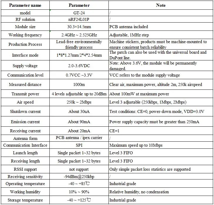
Product Parameters:
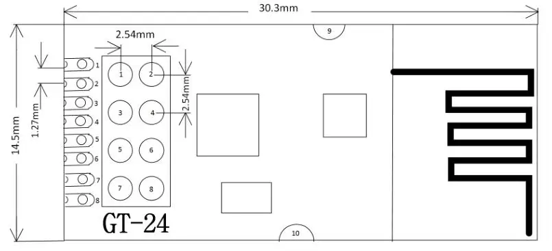
Interface Definition:

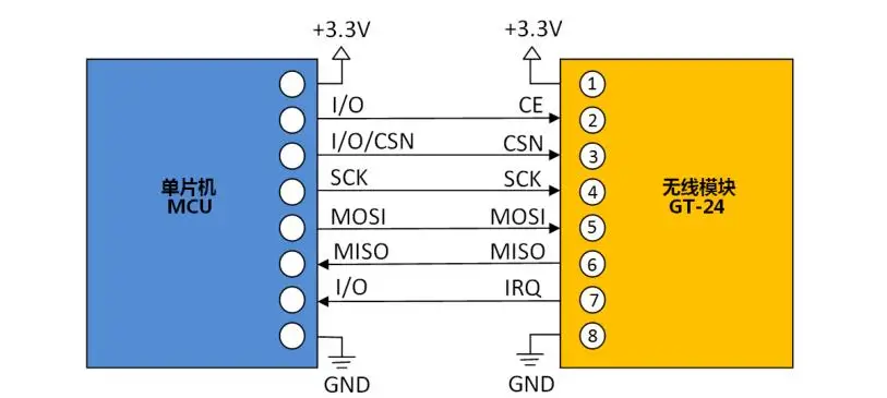
Typical circuit connected to single chip microcomputer:
-
This module is nRF24L01P+PA+LNA, and its driving method is completely equivalent to nRF24L01P. Users can operate according to the nRF24L01P chip manual.
-
The CE pin is connected to the LNA enable pin. When CE=1, the LNA is turned on. When CE=0, the LNA is turned off. This operation is completely consistent with the transmission and reception mode of the nRF24L01. In other words, users don't have to care about LNA operations at all.
-
CE can be connected to a high level for a long time, but the module must first be set to POWER DOWN power-down mode when writing the register. It is recommended to connect CE to the IO port of the MCU.
-
The IRQ can be disconnected, and the SPI query mode can be used to obtain the interrupt status. However, it is recommended to use an external interrupt from the microcontroller.
-
The module's CE pin timing operation can be as high as 10us mentioned in the nRF24L01P technical manual, but we recommend changing to: SPI operation pre-high CE, until the transmission interrupt is completed, then maintain 1mS high time Then lower the CE. The purpose of this is to immediately switch to the receiving mode after the GT-24 is sent. If CE=0, the LNA is turned off, which will be detrimental to the receiving sensitivity.
-
Note that the grounding is good, there is a large area of paving, the power supply ripple is small, the filter capacitor should be added and as close as possible to the module VCC and GND pins.
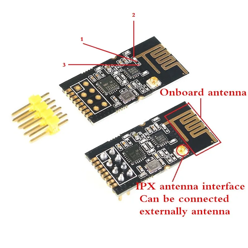
The module uses the onboard PCB antenna by default. The chip inductor is soldered to 1, 2 as shown in the figure. If you need to use the ipx carrier to pull out the external antenna, you can put the chip inductor to 1,3 as shown.


