Categories
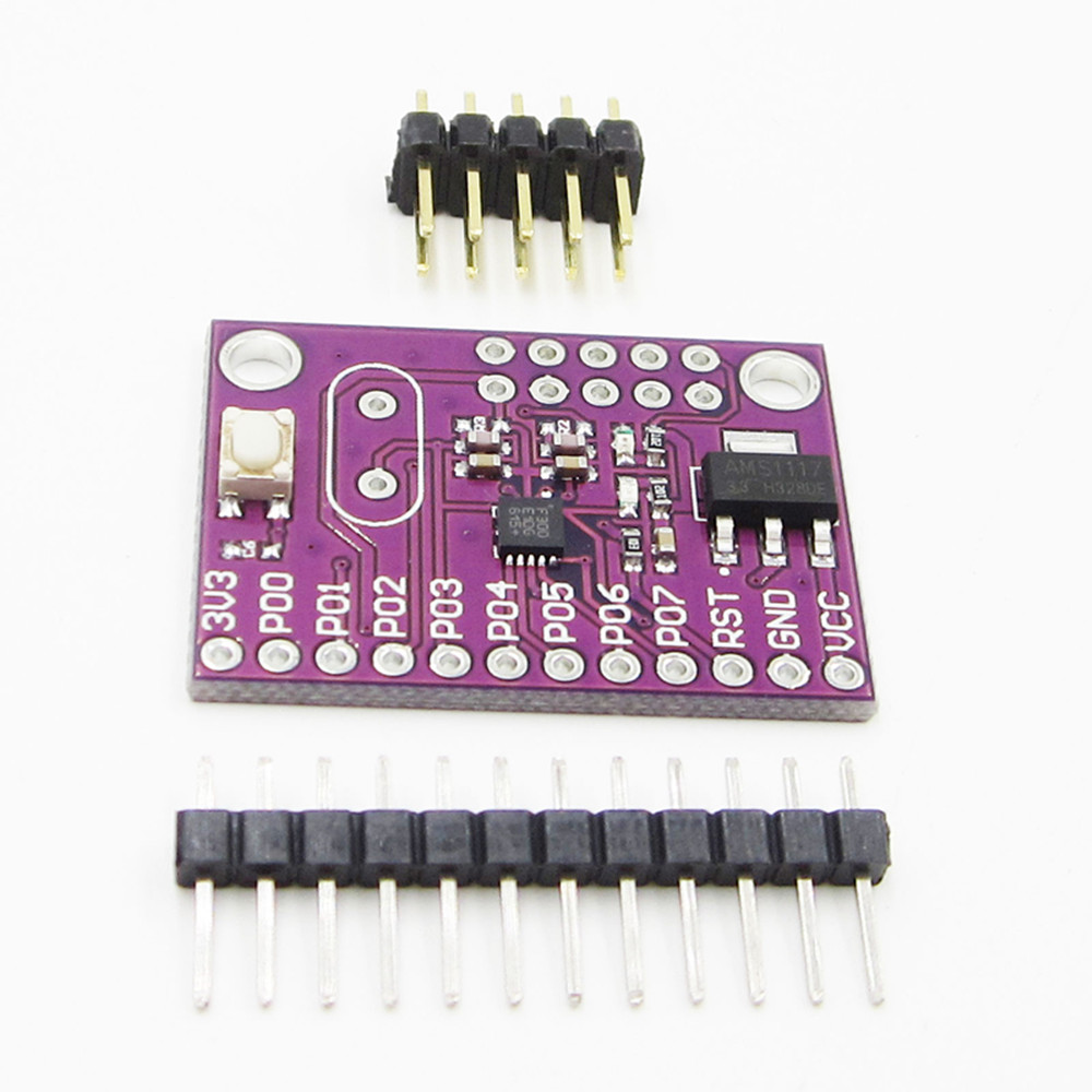
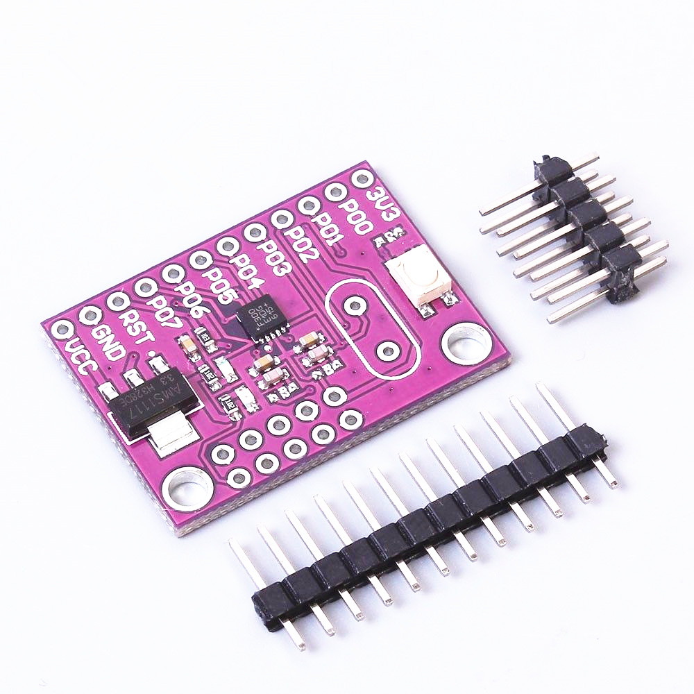
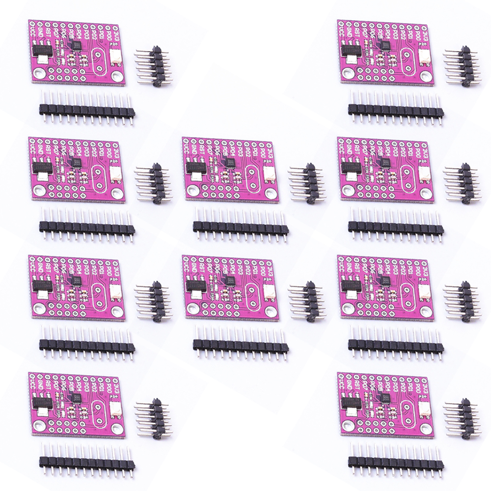
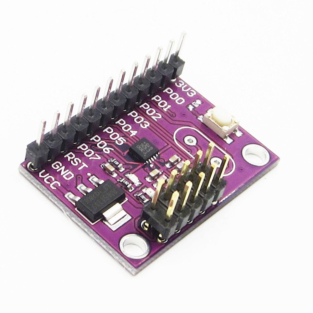
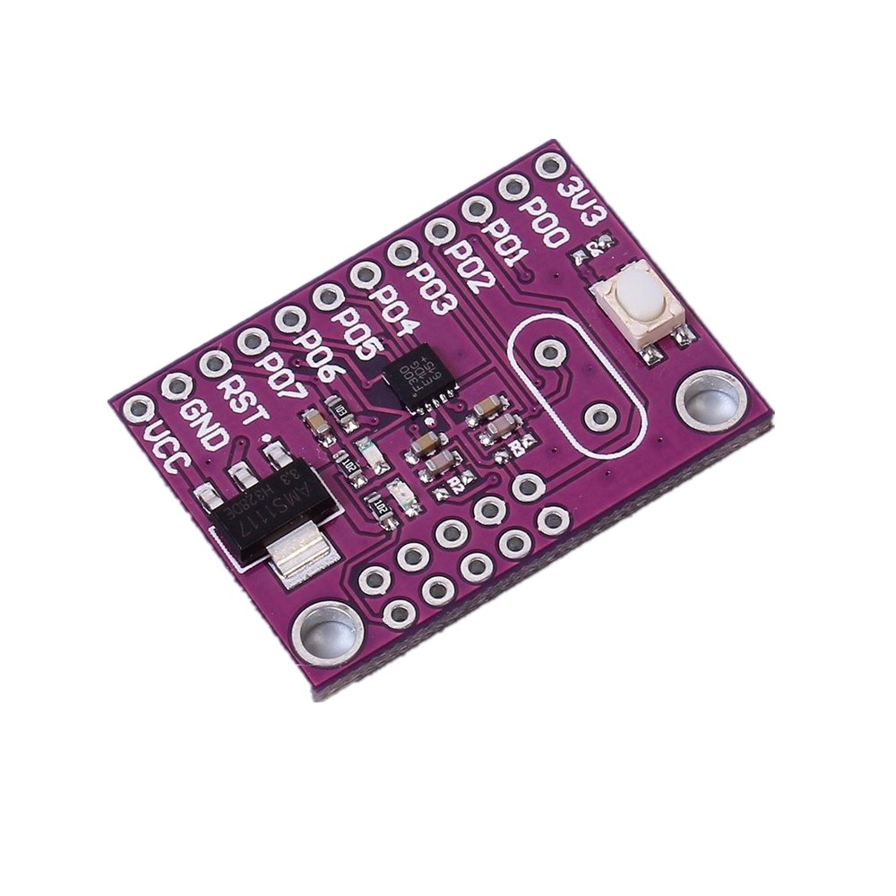
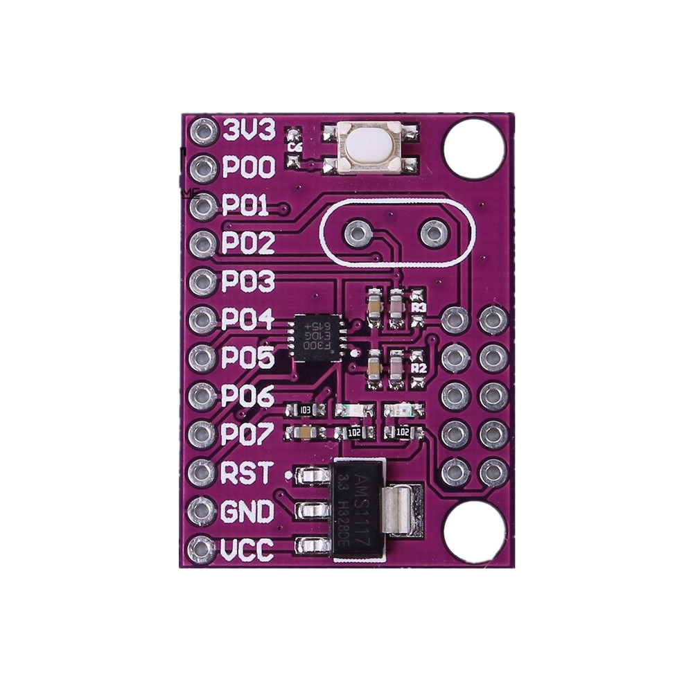
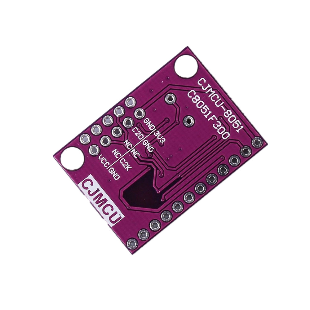
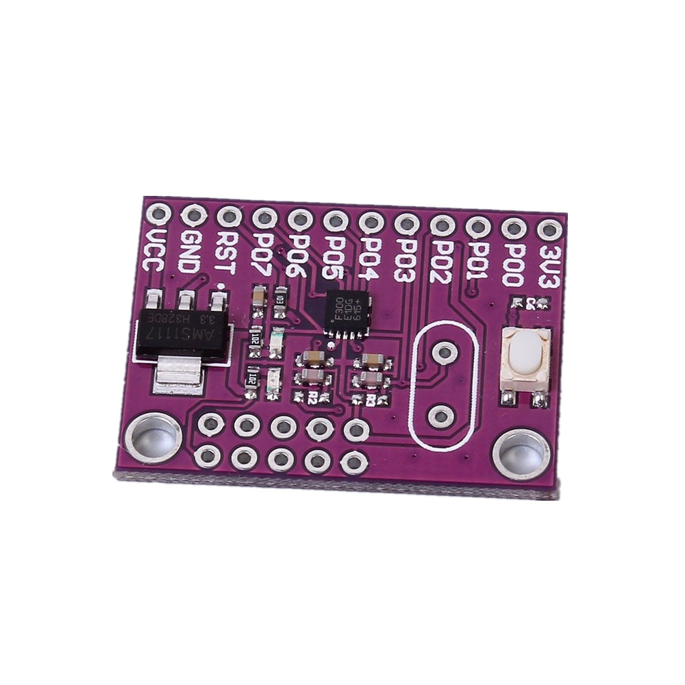
1-10x C8051F300 MCU Micro Control Development Board Industrial Control Module US
Description
Product Introduction:
Analog Peripherals:
8 Bit ADC
1)Up To 500ksps
2)Up To 8 External Inputs
3)Programmable Amplifier Gains Of 4,2,1,0.5
4)VRFF From External Pin Or VDD
5)Built-In Temperature Sensor
6)External Conversion Start Input
8 Bit ADC
1)Up To 500ksps
2)Up To 8 External Inputs
3)Programmable Amplifier Gains Of 4,2,1,0.5
4)VRFF From External Pin Or VDD
5)Built-In Temperature Sensor
6)External Conversion Start Input
Comparator
1)Programmable Hysteresis And Response Time
2)Configurable As Interrupt Or Reset Source
3)Low Current (0.5uA)
1)Programmable Hysteresis And Response Time
2)Configurable As Interrupt Or Reset Source
3)Low Current (0.5uA)
On-Chip Debug
1.On-chip debug circuitry facilitates full speed,non-intrusive in-system debug (no emulatorrequired)
2.Provides breakpoints, single stepping,inspect/modify memory and registers
3.Superior performance to emulation systems using ICE-chips, target pods, and sockets
4.Complete development kit
1.On-chip debug circuitry facilitates full speed,non-intrusive in-system debug (no emulatorrequired)
2.Provides breakpoints, single stepping,inspect/modify memory and registers
3.Superior performance to emulation systems using ICE-chips, target pods, and sockets
4.Complete development kit
Supply Voltage:2.7 to 3.6 V
1.Typical Operating Current:5mA 25 MHz;11uA 32MHz
2.Typical Stop Mode Current:0.1uA
3.Temperature Range:-40℃~85℃
1.Typical Operating Current:5mA 25 MHz;11uA 32MHz
2.Typical Stop Mode Current:0.1uA
3.Temperature Range:-40℃~85℃
High Speed 8051 Core:
1.Pipelined instruction architecture; executes 70% ofinstructions in 1 or 2 system clocks
2.Up to 25 MIPS throughput with 25 MHz clock
3.Expanded interrupt handler
1.Pipelined instruction architecture; executes 70% ofinstructions in 1 or 2 system clocks
2.Up to 25 MIPS throughput with 25 MHz clock
3.Expanded interrupt handler
Memory:
1.256 bytes internal data RAM
2.Up to 8 kB Flash; In-system programmable in 512 byte sectors
1.256 bytes internal data RAM
2.Up to 8 kB Flash; In-system programmable in 512 byte sectors
Digital Peripherals:
1.8 Port I/O; All 5 V tolerant with high sink current
2.Hardware enhanced UART and SMBus serial ports
3.Three general-purpose 16-bit counter/timers
4.16-bit programmable counter array (PCA) with three capture/compare modules
5.Real time clock mode using PCA or timer and external clock source
1.8 Port I/O; All 5 V tolerant with high sink current
2.Hardware enhanced UART and SMBus serial ports
3.Three general-purpose 16-bit counter/timers
4.16-bit programmable counter array (PCA) with three capture/compare modules
5.Real time clock mode using PCA or timer and external clock source
Clock Sources:
1.Internal oscillator:24.5MHz with +/-2% accuracy supports UART operation
2.External oscillator:Crystal,RC,C,or clock (1 or 2 pin modes)
3.Can switch between clock sources on-the-fly
4.Useful in power saving modes
1.Internal oscillator:24.5MHz with +/-2% accuracy supports UART operation
2.External oscillator:Crystal,RC,C,or clock (1 or 2 pin modes)
3.Can switch between clock sources on-the-fly
4.Useful in power saving modes
List
1/2/5/10PCS Board With Pin
1/2/5/10PCS Board With Pin
