Categories
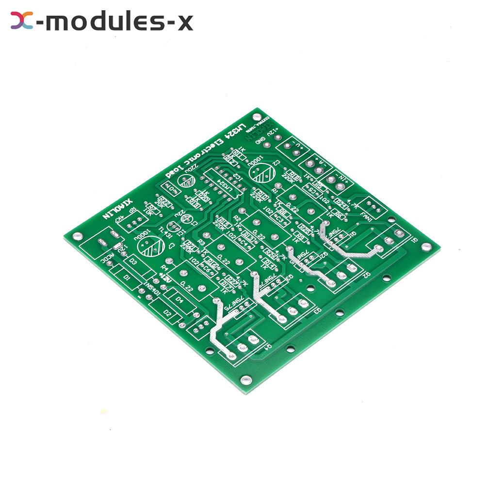
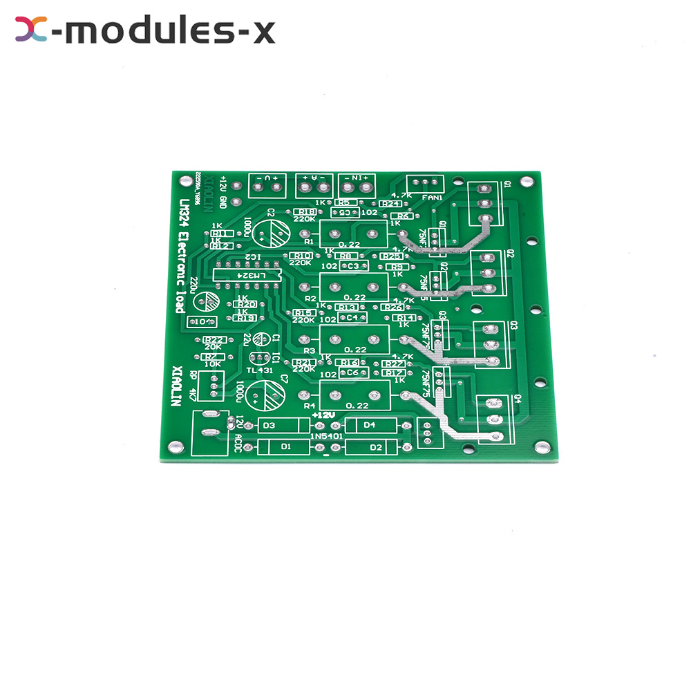
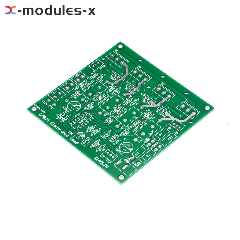
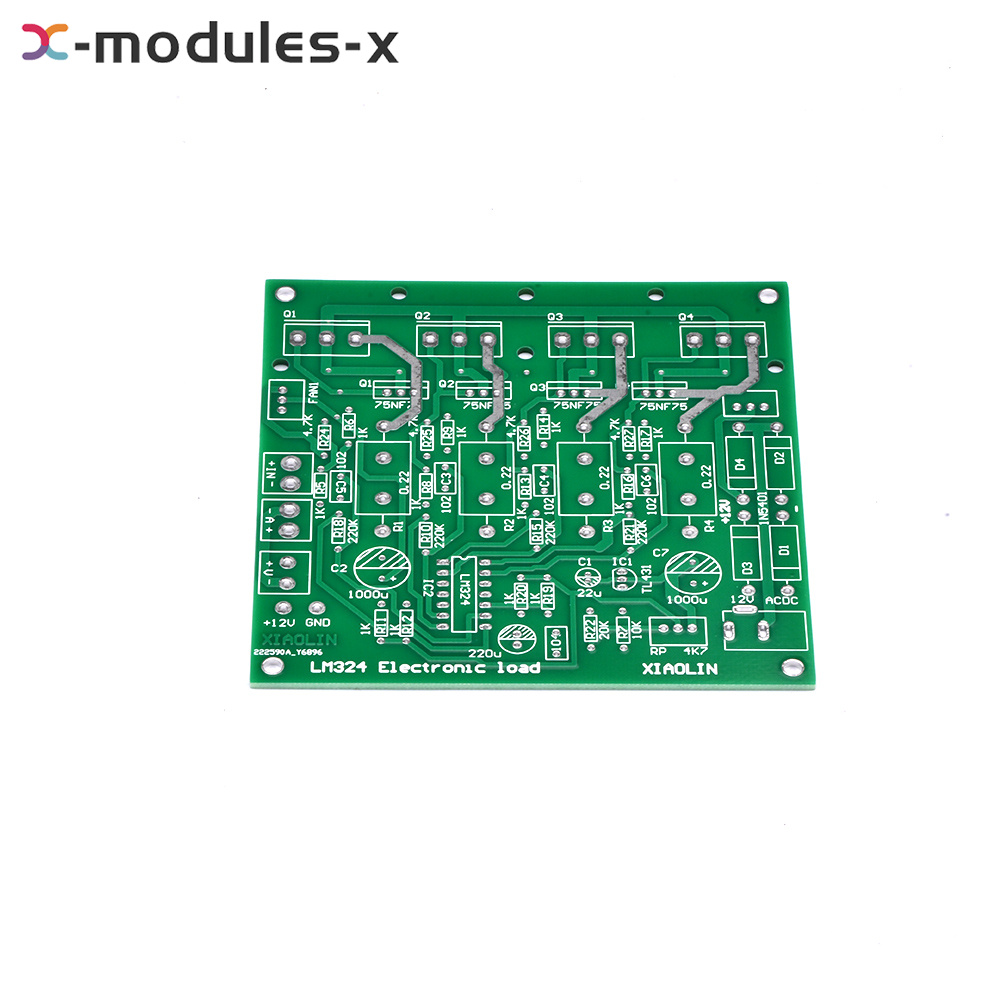
Electronic Load Test Board Kit Constant Current Discharge 150W 15V 10A Circuit
Description
Product features:
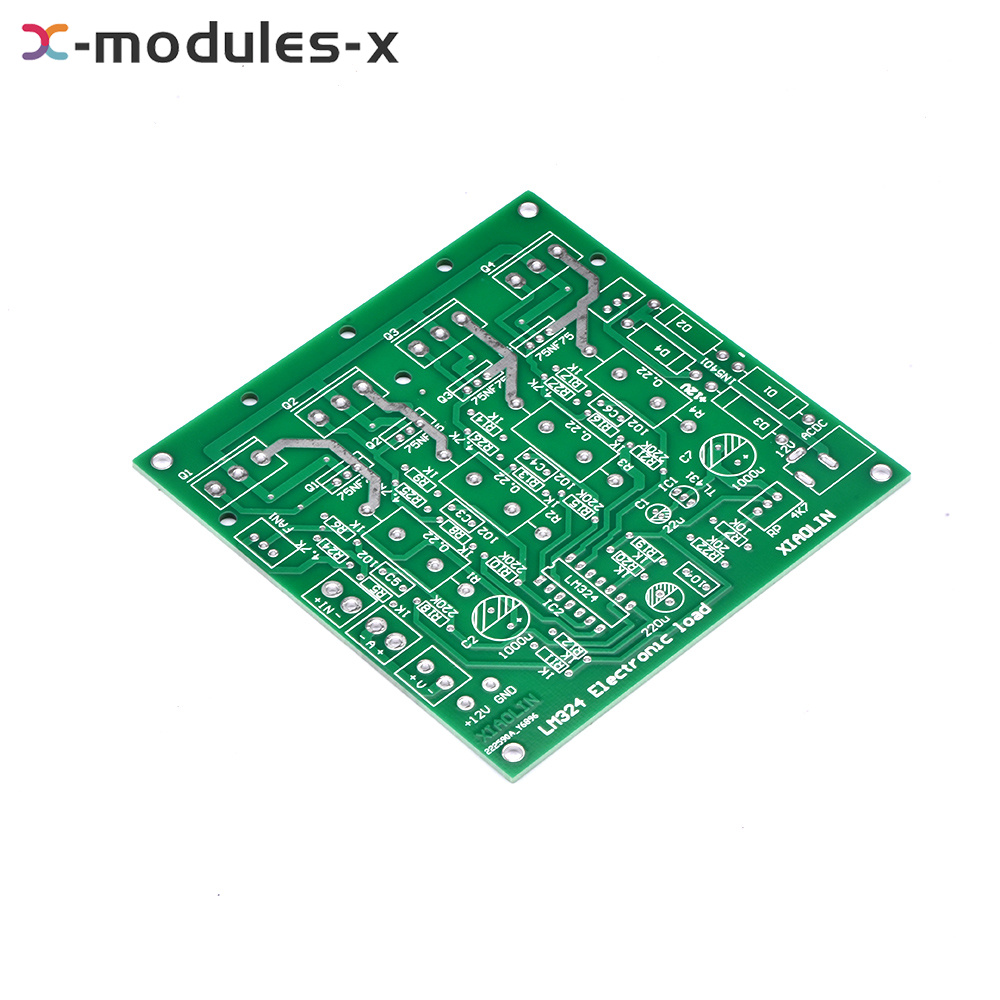
1. The basic circuit form is that TL431 provides the reference voltage, current detection resistance, LM324 operational amplifier error amplification, and together with MOS tube forms a constant current circuit.
2. Four MOS tubes are used for CPU heat sink
3. Four 110N8F6 110A 80V packaged with T0-220
4. Replacement: Model 80NF70 IRF3205 HRF3250 IRF1010 IRF2807IRF1405 047an08ao, etc., or TO-247 high-power package tube such as IRF 250 260
5. The DIY kit circuit is simple, reliable and practical, and is applicable to all kinds of enthusiasts DIY
Product parameters:
Input voltage: 0-15v/0-72V
Load current: 0-10A/0-2A
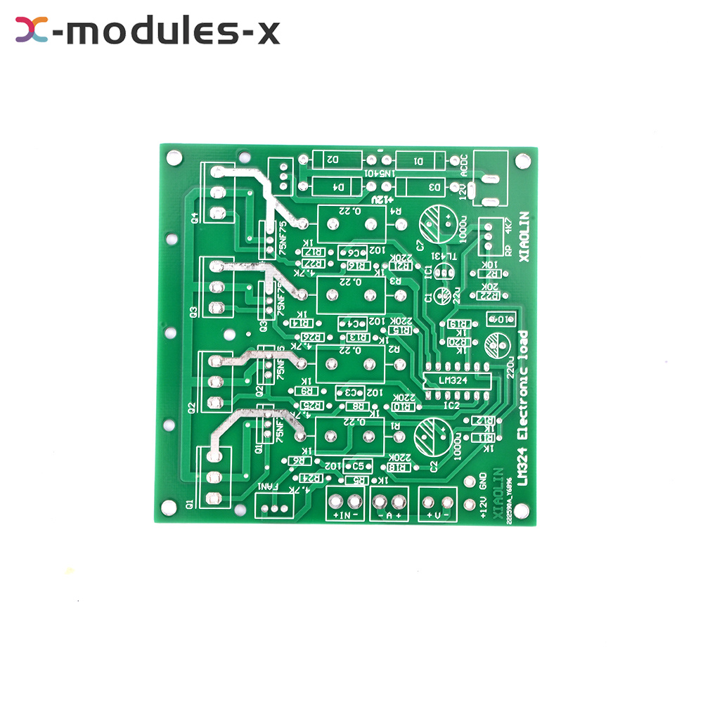
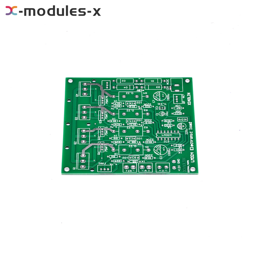
Parameters of the original circuit diagram: 75NF75 75V 75A 150W
PCB board size: 10 * 10cm
Note:
It is required to provide: 12v transformer or switching power supply and dual-display meter head, red and black wiring posts, heat sink (available CPU heat sink, one is 75W), or power amplifier and power supply and other disassembled heat sink;
The voltage is the range of the voltage value of the incoming power supply, which is not adjustable.
The current is adjustable for this load test. After the desired value is adjusted, the constant current is tested.
Test the maximum discharge current of the power supply, check whether the power supply current is in line with the standard, and test the aging of the power supply products.
The amount of W depends on the power dissipation of the NMOS tube. The board voltage is within 300V, and the power can also be increased by multiple blocks in parallel.
Operating instructions:
1. When the board is powered by 12V switch power supply, the wire can be welded to the right+-.
Or weld the DC base and short it to the+- welding spot with 2 wires. 4 rectifier tubes can not be welded!!!
2. The heat sink cannot be connected with the negative metal of 12V DC base, and both cannot be connected with the metal shell at the same time!!
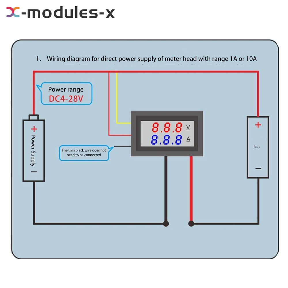
3. When the board is connected to the digital double-display meter head, the thin red wire of the meter head is connected to the small word at the left end of the board:+12V
Note: Do not connect the thin black wire to GND! (The current will not be accurate)!!!
4. A+- thick red and black line of current connected to the meter head V+thin yellow line of voltage test connected to the meter head, IN is the test input terminal, and the red and black test terminal is connected to the tested power supply. The FAN terminal is connected to the cooling fan.
5. Pry off the cap with the knob and tighten it with screws.
6. The power pipe is coated with thermal conductive silicone grease and directly screwed to the radiator. The radiator must be connected before power-on commissioning! Otherwise, the power tube may be burnt!
Notes for use:
1. The positive and negative poles of the tested power supply must not be connected reversely, or the MOS power tube will be burned and broken!
2. Anti-reverse connection: a high-current diode such as 20A10 is welded to the positive pole of the input terminal IN of the board
3. When the current is high, the diode in series is hot for a long time, and the pin tin can sometimes turn into faulty soldering.
4. Circuit diagram of this kit: R22 can be replaced by 16K-18K, and the test current can be increased to 10A, now 20K is 8A, and C1 with 22uF
5. If the heat sink is fixed to the PCB board, pad a heat-resistant insulating sheet to prevent short circuit of TO-247 pad on the PCB board.
6. For computer heat sink and hard disk bracket, simply install a shell, and heat dissipation must be done well
Hole of heat sink:
Prefabricated hole size=tap outer diameter - tap pitch, M3 screw pitch (metric) is 0.5mm, so use φ Drill with 2.5 bit and tap with M3 tap.
Anti-reverse connection: 1. The positive pole of the input terminal is connected with a high-current diode in series, such as 20A10 If the anti-reverse connection secondary tube is connected, please note that the fine yellow line of the voltmeter should be connected to the positive pole of the power supply to be measured at the outside of the diode.
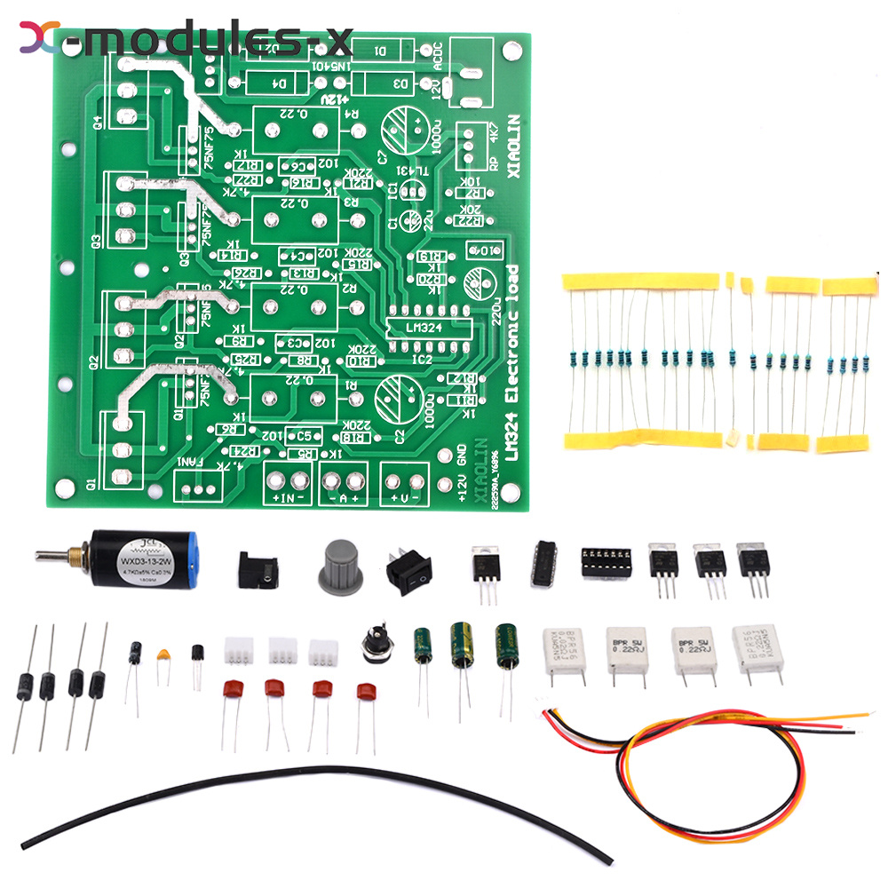
Product list:
1X kit (1XPCB+all components)
Electronic Load Test Board Kit Constant Current Discharge 150W 15V 10A Circuit
Description
Product features:
1. The basic circuit form is that TL431 provides the reference voltage, current detection resistance, LM324 operational amplifier error amplification, and together with MOS tube forms a constant current circuit.
2. Four MOS tubes are used for CPU heat sink
3. Four 110N8F6 110A 80V packaged with T0-220
4. Replacement: Model 80NF70 IRF3205 HRF3250 IRF1010 IRF2807IRF1405 047an08ao, etc., or TO-247 high-power package tube such as IRF 250 260
5. The DIY kit circuit is simple, reliable and practical, and is applicable to all kinds of enthusiasts DIY
Product parameters:
Input voltage: 0-15v/0-72V
Load current: 0-10A/0-2A
Parameters of the original circuit diagram: 75NF75 75V 75A 150W
PCB board size: 10 * 10cm
Note:
It is required to provide: 12v transformer or switching power supply and dual-display meter head, red and black wiring posts, heat sink (available CPU heat sink, one is 75W), or power amplifier and power supply and other disassembled heat sink;
The voltage is the range of the voltage value of the incoming power supply, which is not adjustable.
The current is adjustable for this load test. After the desired value is adjusted, the constant current is tested.
Test the maximum discharge current of the power supply, check whether the power supply current is in line with the standard, and test the aging of the power supply products.
The amount of W depends on the power dissipation of the NMOS tube. The board voltage is within 300V, and the power can also be increased by multiple blocks in parallel.
Operating instructions:
1. When the board is powered by 12V switch power supply, the wire can be welded to the right+-.
Or weld the DC base and short it to the+- welding spot with 2 wires. 4 rectifier tubes can not be welded!!!
2. The heat sink cannot be connected with the negative metal of 12V DC base, and both cannot be connected with the metal shell at the same time!!
3. When the board is connected to the digital double-display meter head, the thin red wire of the meter head is connected to the small word at the left end of the board:+12V
Note: Do not connect the thin black wire to GND! (The current will not be accurate)!!!
4. A+- thick red and black line of current connected to the meter head V+thin yellow line of voltage test connected to the meter head, IN is the test input terminal, and the red and black test terminal is connected to the tested power supply. The FAN terminal is connected to the cooling fan.
5. Pry off the cap with the knob and tighten it with screws.
6. The power pipe is coated with thermal conductive silicone grease and directly screwed to the radiator. The radiator must be connected before power-on commissioning! Otherwise, the power tube may be burnt!
Notes for use:
1. The positive and negative poles of the tested power supply must not be connected reversely, or the MOS power tube will be burned and broken!
2. Anti-reverse connection: a high-current diode such as 20A10 is welded to the positive pole of the input terminal IN of the board
3. When the current is high, the diode in series is hot for a long time, and the pin tin can sometimes turn into faulty soldering.
4. Circuit diagram of this kit: R22 can be replaced by 16K-18K, and the test current can be increased to 10A, now 20K is 8A, and C1 with 22uF
5. If the heat sink is fixed to the PCB board, pad a heat-resistant insulating sheet to prevent short circuit of TO-247 pad on the PCB board.
6. For computer heat sink and hard disk bracket, simply install a shell, and heat dissipation must be done well
Hole of heat sink:
Prefabricated hole size=tap outer diameter - tap pitch, M3 screw pitch (metric) is 0.5mm, so use φ Drill with 2.5 bit and tap with M3 tap.
Anti-reverse connection: 1. The positive pole of the input terminal is connected with a high-current diode in series, such as 20A10 If the anti-reverse connection secondary tube is connected, please note that the fine yellow line of the voltmeter should be connected to the positive pole of the power supply to be measured at the outside of the diode.
Product list:
1X kit (1XPCB+all components)
