
For various applications, the developed general data acquisition module is widely used in various industries such as building, HVAC, fire protection, water supply, petrochemical, environmental protection, etc. It is used by most system integrators, automation companies and research institutes. High character ratio, stable and reliable data acquisition module. Special applications Customers who need cooperation, please contact us!
=> Support multiple types of PLC;
=> Support configuration software such as Kingview, Force Control, MCGS;
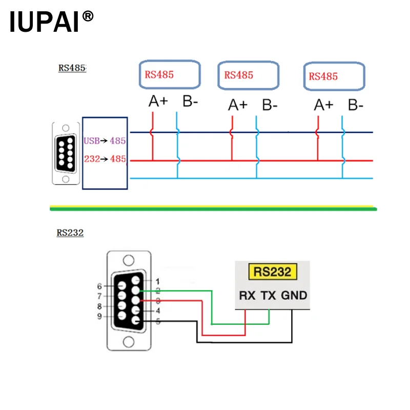
=> Support RS232, RS485 interface, Modbus protocol touch screen, text screen;
=> Support all standard Modbus devices online communication;
=> If you buy a large quantity, support custom function modules;
=> R&D personnel directly face customer technical support and assist customers to complete the project;

CPU: imported chip, 32-bit ATMEL ARM high-speed processor, 72MHZ
Operating system: GCOS, 10ms scheduling mechanism
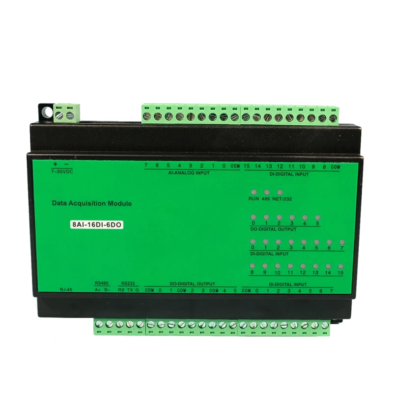
Power supply voltage: 7-35VDC @2W, power reverse polarity protection, isolation design
Communication interface: DCDC isolation design, 2500V lightning protection, ESD, overvoltage, overcurrent protection
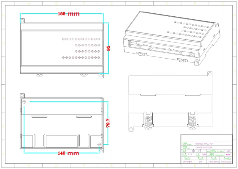
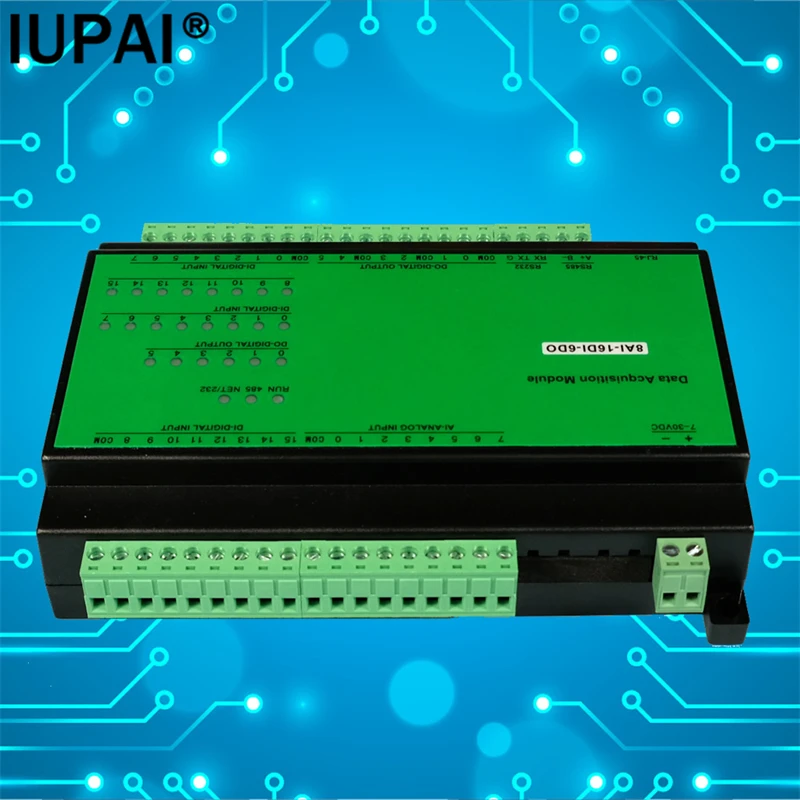
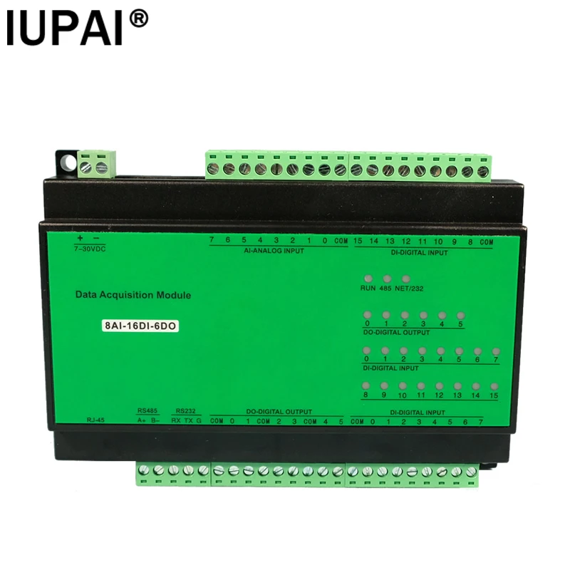
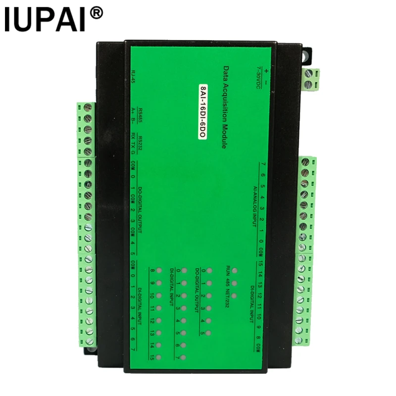
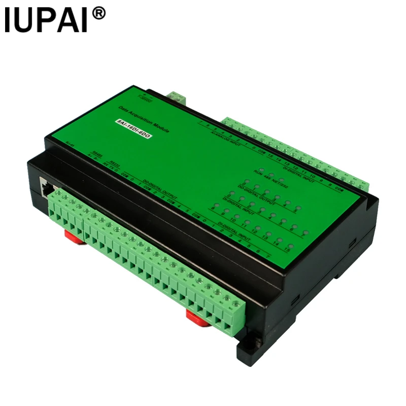
Dimensions: Volume (L x W x H): 155 x 95 x 39 (mm)
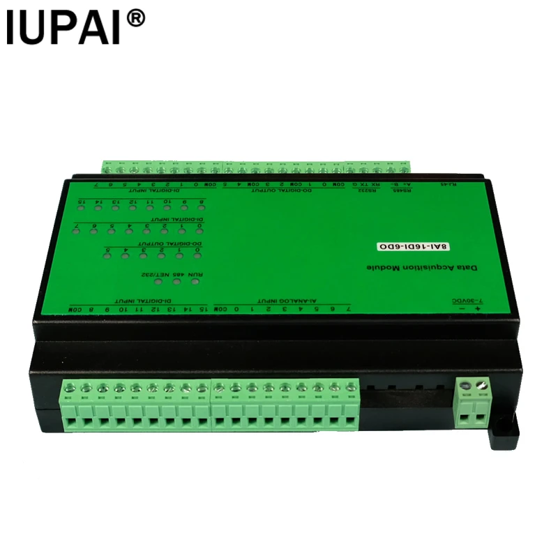
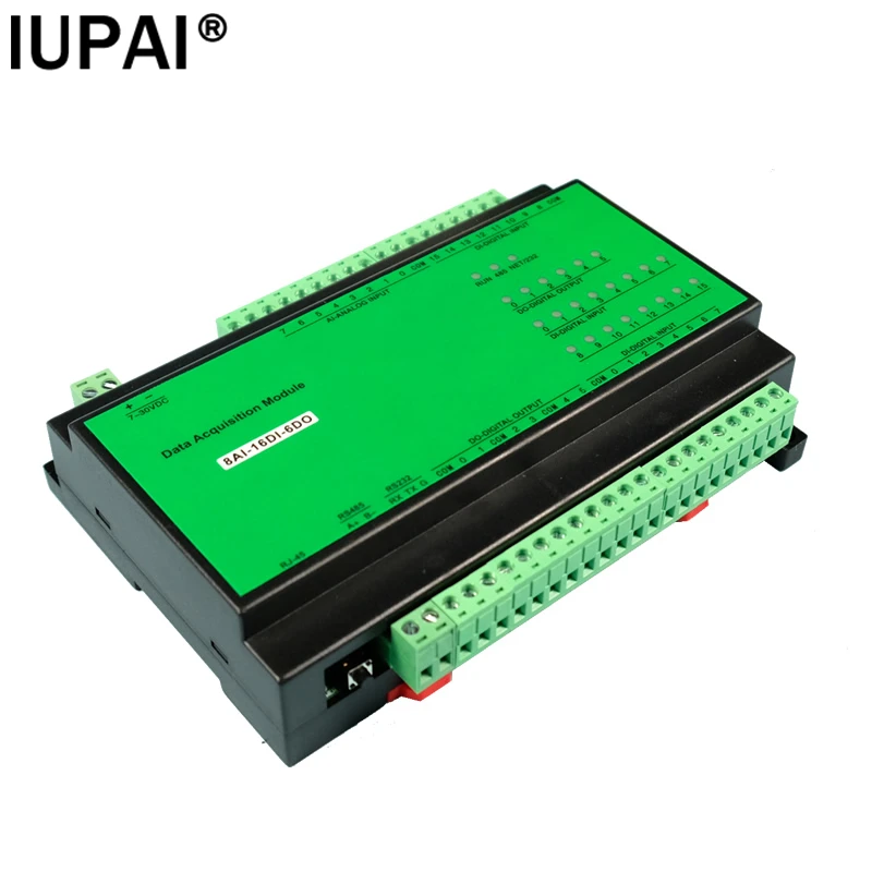
Installation method: screw fixing or rail installation
Environmental index: -40~85℃, 5%~95%RH non-condensing, IP20 protection
Hardware watchdog: 1.5 seconds hardware watchdog protection system
Channel isolation: 2500VDC isolation, anti-interference protection design. Since 1997, the product has been used stably in industrial sites


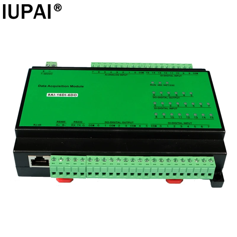
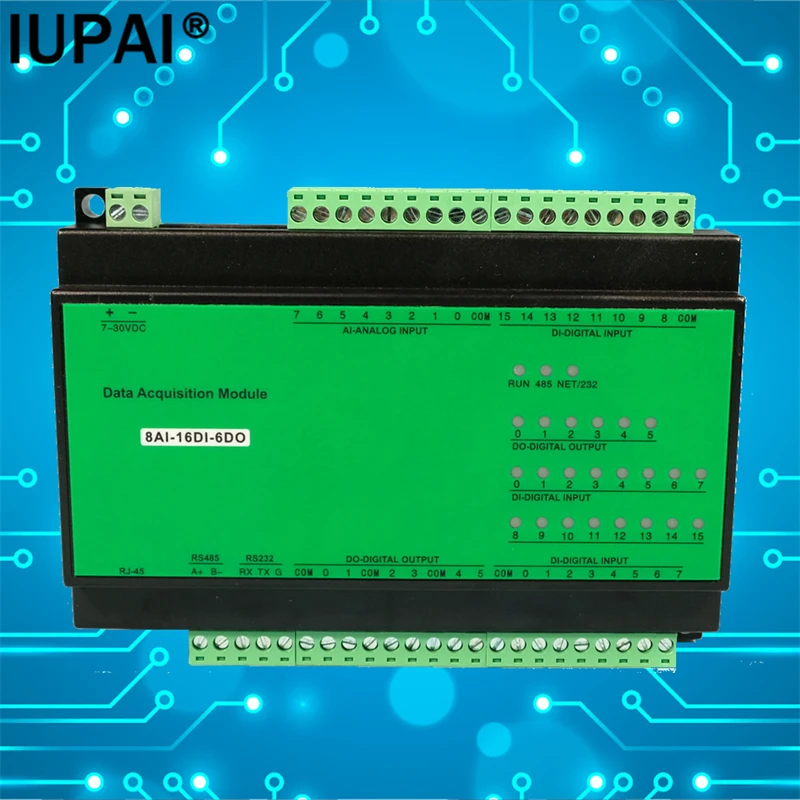
Communication interface: RJ45 interface
Communication protocol: standard MODBUS TCP protocol
Communication rate: communicate with the host computer, more than 1000 times/second
Communication bandwidth: 10M/100Mbps, real high-speed Ethernet
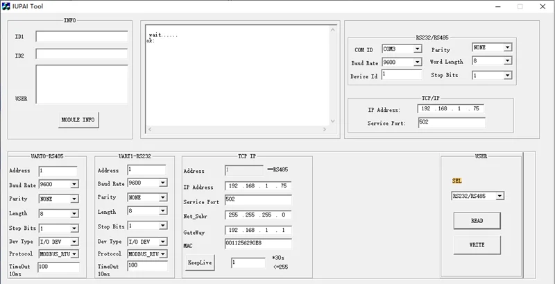
IP address: 192.168.1.75
Port number: 502
Support network cable: both crossover network cable and direct connection network cable are available, and the module can be self-adaptive

Number of channels: 1 RS485, 1 RS232
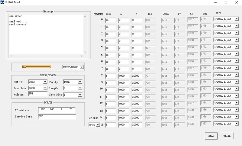
Baud rate: 1200~115200, default 9600
Parity check: odd check, even check, no check
Start bit: 1 bit
Data bits: 8 bits
Stop bits: 1, 2 bits
Communication protocol: MODBUS RTU
Default parameter: 9600.N.8.1, station number: 1

POWER light: Displays the power status
RUN light: module running indication, flashes once per second
485 light: RS485 sending data indication
NET light: Ethernet communication indication
IO light: each channel of digital IO has a corresponding indicator light

Modbus address: 40051--40058
Function code: 03, address: 50
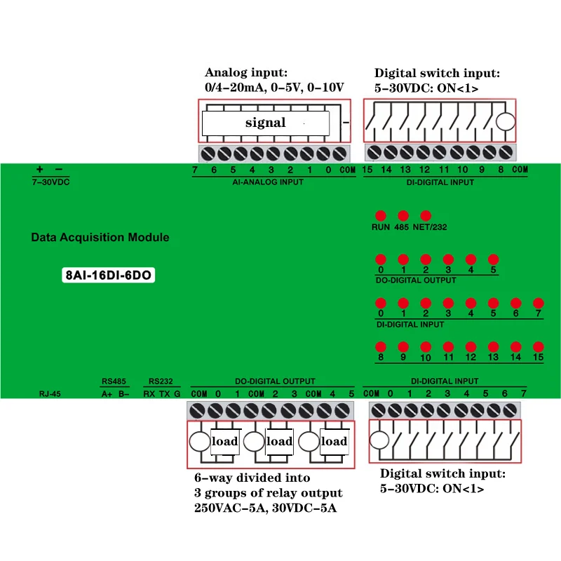
Factory Default: Current Input: 4-20mA, 0-20mA [Compatible]
Voltage input: 0-5V, 1-5V, 0-10V
Change the type in two steps:
1. Open "AI Configuration Software" and select the type;
2. Open the module cover, each channel has a jumper cap:
---Short 2 pins on the side of the 'chip': "voltage type"
---Short 2 pins on the 'terminal' side: "current type"
Data precision: 0.1% precision, 12 bits
Refresh frequency: 0.1 seconds to update all I/O point data
The corresponding value divided by 1000 is the actual signal size:
4~20mA: 4000~20000 <16-bit integer>
0~20mA: 0000~20000
0~5V: 0000~5000
0~10V: 0000~10000
Current and voltage calculation formula:
Register reading / 1000
Example: read 40051 register data == 4000
Then the corresponding current = 4000 / 1000 = 4mA
Two-wire connection:
The meter is connected to the positive power supply;
The instrument is negatively connected to AI;
The power supply is negatively connected to AI-COM;
Three-wire connection:
The meter is connected to AI;
The instrument is negatively connected to COM;
Four-wire connection:
The meter is connected to AI;
The instrument is negatively connected to COM;

Function 1: Modify the corresponding value;
Factory default 4-20mA correspondence: 4000-20000 <register>
Function 2: Modify the signal type:
0-5V, 1-5V, 0-10V, 0-20mA;
4-20mA minimum 0mA: AI=0 when the wire is disconnected, it is convenient for users to check whether the wiring is bad;
4-20mA minimum 4mA: AI=4mA when disconnected, that is, AI reading is always greater than 4mA;

Modbus address: 10001~10016: Corresponding channel number
Function code: 02, address: 0
Input method: optocoupler isolation
ON level: 5-30VDC, 6mA@24VDC
OFF level: 0-3VDC
Isolation voltage: 2500V, lightning protection circuit + optocoupler isolation + overrun protection
Sampling rate: 0.01 seconds to quickly collect all channel data
Wet Node Wiring Method
Both NPN/PNP sensors can be connected: COM can be connected to positive or negative
Dry Node Wiring Method
One end of the customer's switch equipment is connected to the positive power supply of the module, the other end is connected to DI, and the DICOM is connected to the negative power supply of the module.
Detection scheme
1. The module power supply is connected to DI, and the module power supply is negatively connected to DICOM
2. "Module test software.exe" test reading
3. The signal can be read to indicate that the DI function is normal
4. If the signal cannot be read, use a multimeter to measure whether there is a 5-30V voltage across DI and COM

Modbus address: 00001-00006
Function code: 05, 15
Output mode: normally open relay 5A/220VAC/30VDC
Isolation design: optocoupler isolation + relay isolation
Response time: ≤0.01 seconds
Mechanical life: rated 20 million times <Hongfa relay>
Detection scheme
1. Open "Module Test Software.exe"
2. Control each relay to open and close
3. The corresponding indicator lights will dim and brighten