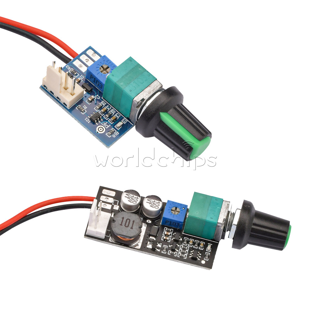
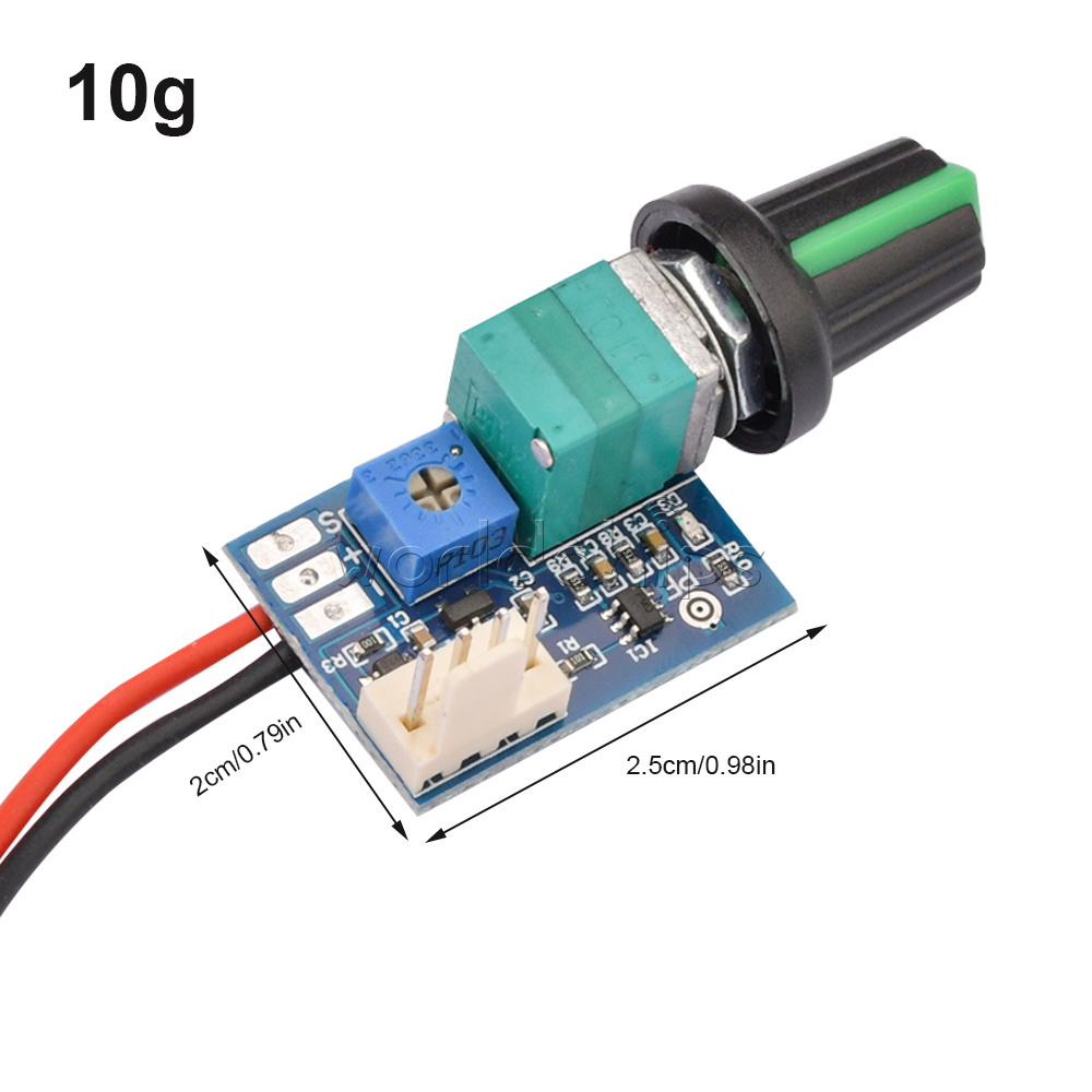
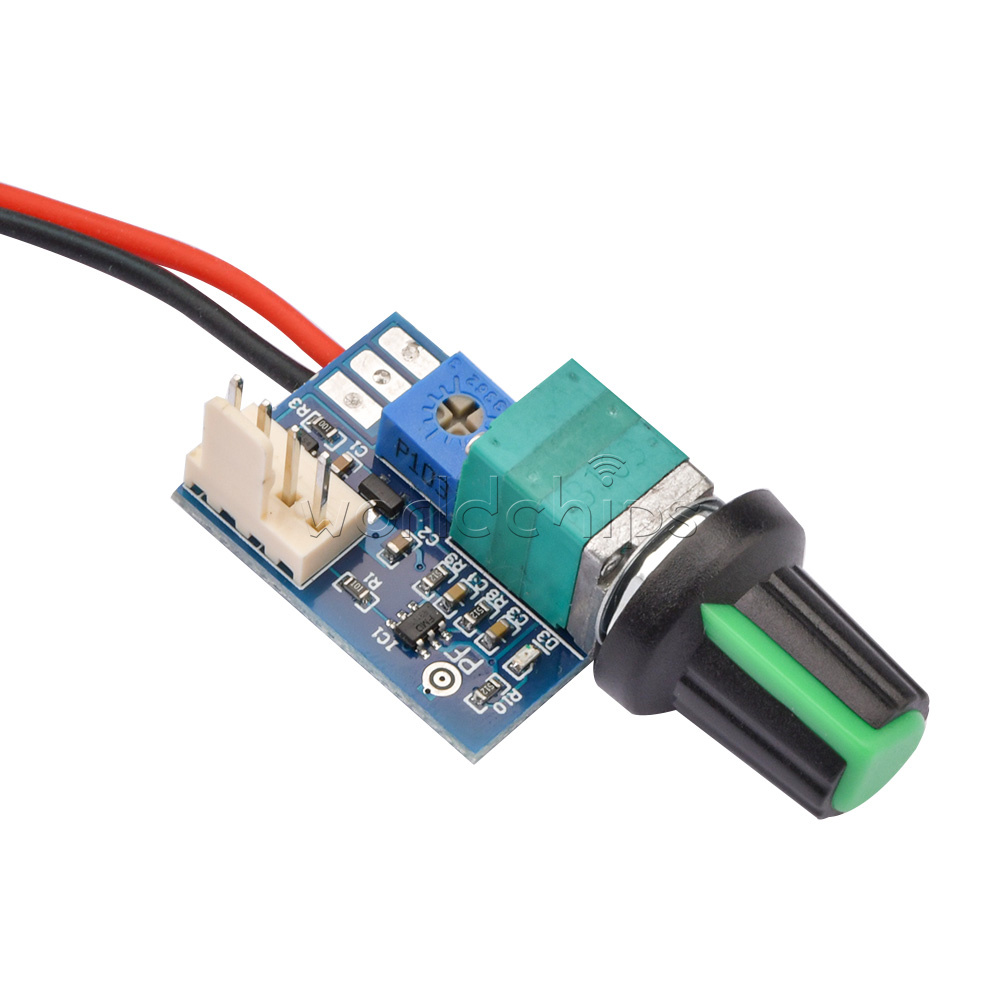
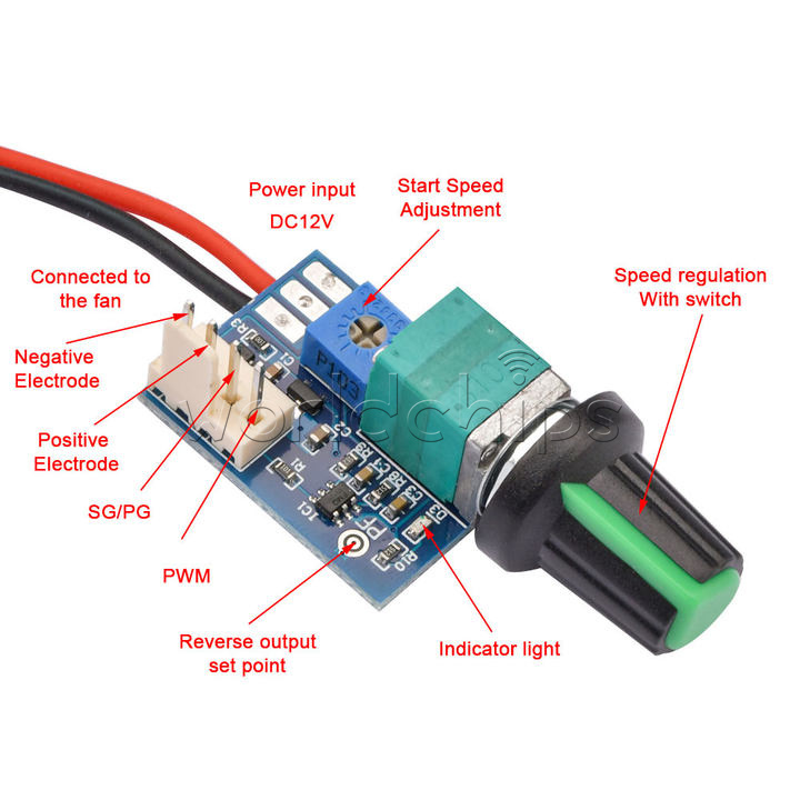
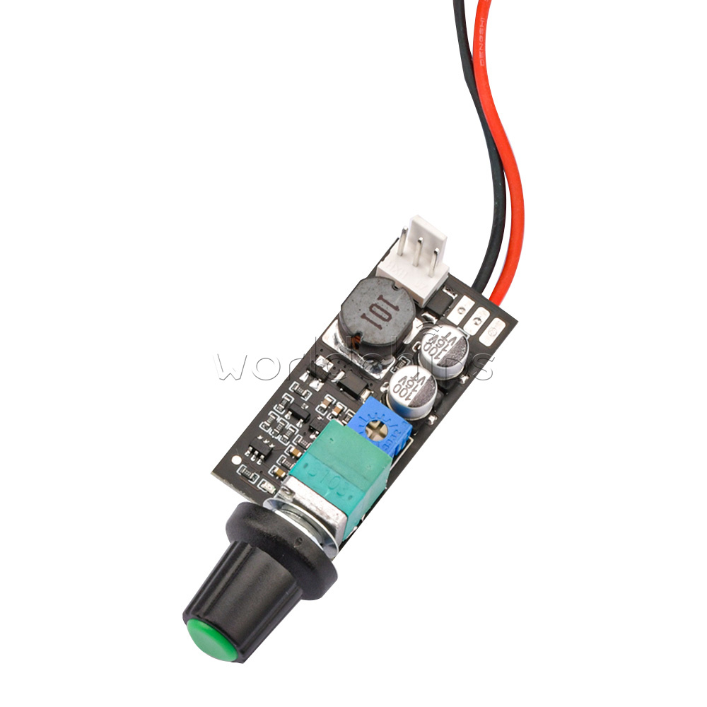
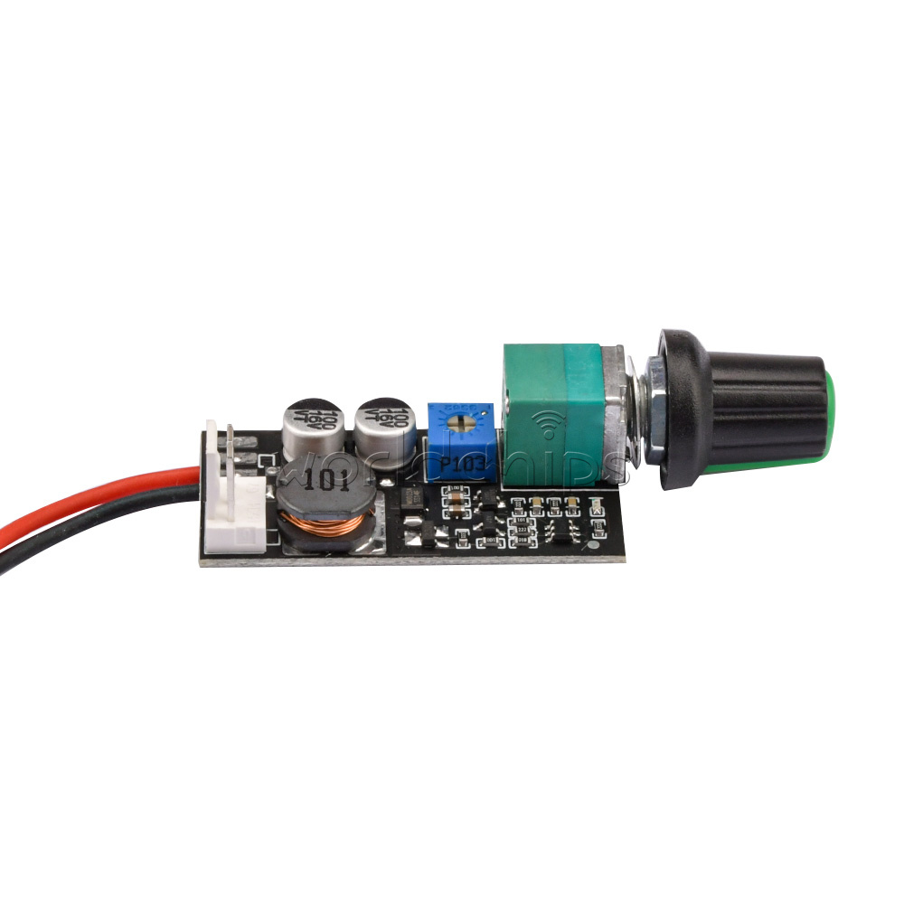
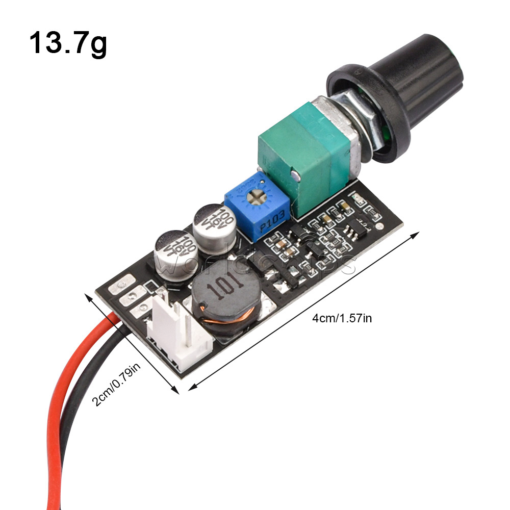
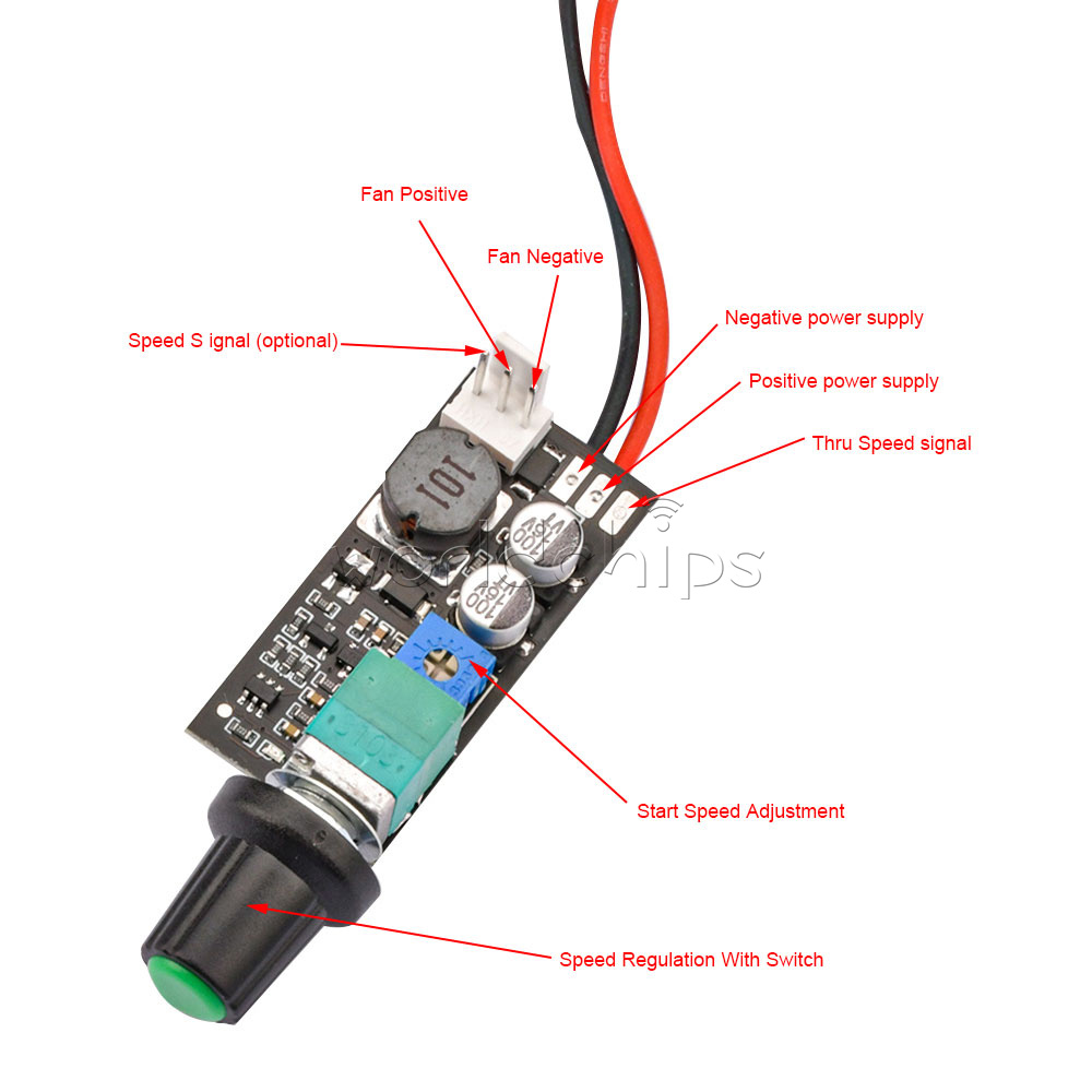
DC12V 4 Wire
Descripion:
Working voltage: DC12V (can work under 8-15V voltage, please pay attention to the same fan voltage)
Fan current: no more than 3A, this current is limited by switches and connectors, and can be expanded by power lines alone
Loss of circuit board itself: less than 20mA without fan
PWM signal mode: 5V25KHZ
PWM signal output range: 0%-100%
Start position PWM adjustment range: 0%-60%
Output interface model: 2510-4P dislocation, conventional CPU, chassis fan socket, pin spacing 2.54mm
Function Description:
Pay attention to the positive and negative poles and the power supply voltage. After the power supply fan is connected, it can be used. The potentiometer is turned off counterclockwise to the end, and the clockwise end is the maximum output.
A separate small adjustable resistor (starting speed adjustment) on the board is used to adjust the speed of the just-open position
If the speed change of the fan is opposite to the adjustment direction, it means that the fan is a reverse-sequence fan, and the (PF) setting point needs to be short-circuited with solder, and the power must be cut off before operation to avoid damage! The short-circuited PWM signal changes in the reverse direction with the adjustment, and the reverse-sequence fan can realize forward adjustment.
Precautions:
This is a four-wire PWM fan speed controller. It can only control 12V four-wire fans that support PWM speed regulation. For example, many 12V four-wire chassis or CPU fans cannot control 2-3-wire fans.
This is a four-wire PWM fan speed controller. It can only control 12V four-wire fans that support PWM speed regulation. For example, many 12V four-wire chassis or CPU fans cannot control 2-3-wire fans.
Package Include:
Module *1

Package include:
Module X1


Module *1
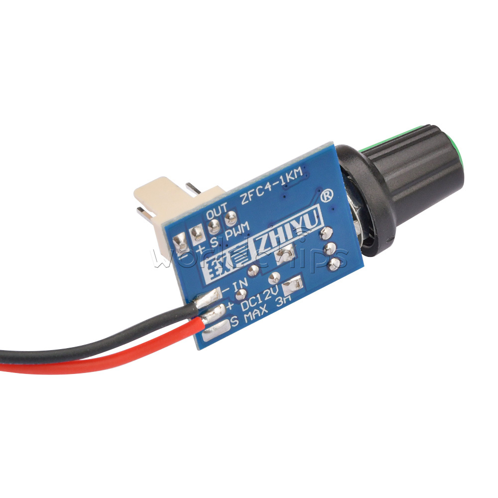
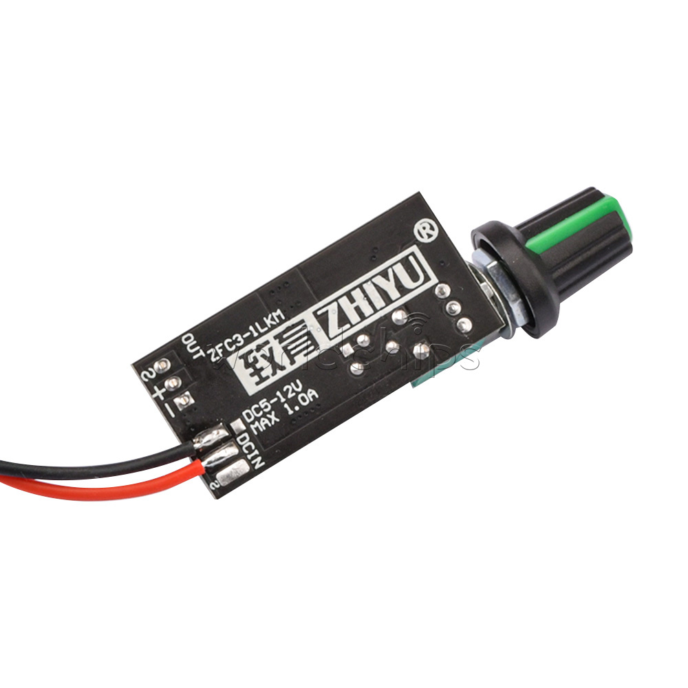
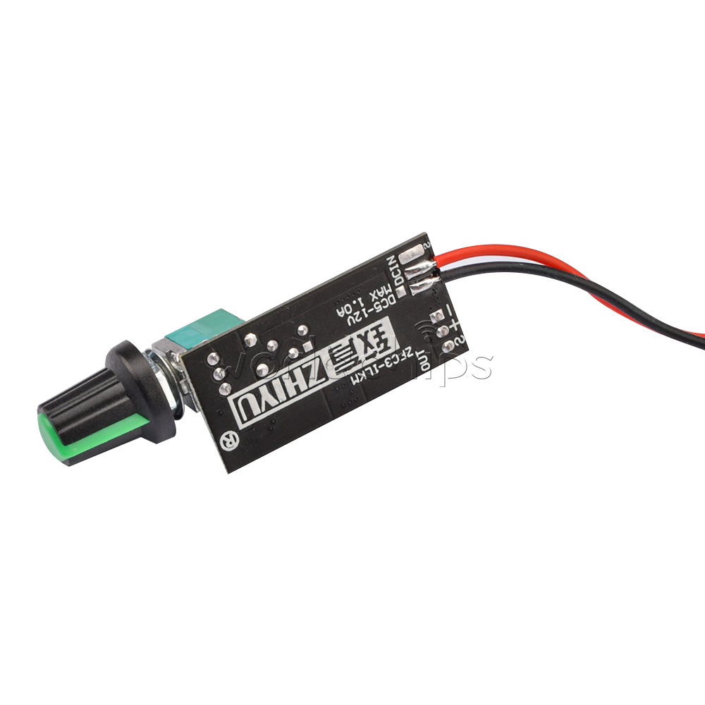
DC5-12V1A 2-3 Wire
Description:
Working voltage: DC5-12V (DC4.7-14V)
Fan current: 0.1-1A Fan current is lower than 0.1A, the control effect is slightly poor, and over 1A may damage the circuit board
Self loss, less than 30mA without fan
Starting position adjustment range: 0%-60% (internal circuit control parameters)
Output interface model: 2510-3P, spacing 2.54mm, conventional CPU, chassis fan socket
Function Description:
Pay attention to the positive and negative poles and the power supply voltage (reverse connection will damage the board), it can be used after the power supply and fan are connected, the potentiometer is turned off counterclockwise to the end, and the clockwise end is the maximum output
A separate small adjustable resistor (initial speed adjustment) on the board is used to adjust the speed at the just-open position. The input of the speed signal port is directly connected to the output of the fan. It is mainly used to guide the fan speed signal back to the main board of the device to detect the speed. No connection between controller circuits
Precautions:
Do not control the fan with more than 1A, do not connect the wrong or reverse power supply, do a good job of insulation to avoid output short circuit
Do not control the fan with more than 1A, do not connect the wrong or reverse power supply, do a good job of insulation to avoid output short circuit
Package include:
Module X1