Description
Welcome to the MOFI-Acoustics store. In order to provide better shopping experience, let me clarify these informations to avoid unnecessary inconvinience:
1. All products in the store are not included: customs duties, customs clearance fees and tax. Without special requirements, we will declare them according to the price of the product.
2. We hope that you can understand the relevant taxation policies of your local customs. We do not accept your refusal for goods due to customs taxation issues; (in some countries, the platform has the option of pre-collecting tariffs).
3. In order not to affect your receipt of the goods, after purchasing the goods, please pay more attention to information such as emails, platform messages, etc. If there is any information about the unclear address or the logistics policy changes, we will notify you as soon as possible, and look forward to you reply.
DIY KIT Project
To complete this project, high level knowledge of electronics and rich experience in terms of soldering and testing are required.
Due to time zone and language communication restrictions, we can only provide limited technical support, and you need to solve problems by yourself.
We do not provide information other than the product introduction page.
MOFI-Shure-Phono-Amplifier(MM)) DIY KIT Project
-Summary
MOFI-Shure-Phono Amp(MM), It is based on the core circuit of the Shure phono amplifier.
-Tech highlights
Compared with the commonly reproduction of Shure, we improved:
1)、High Voltage:Two-stage buck regulator filter, Two low-pass filter (with a corner frequency of 1.6Hz&16Hz) prevents power noise from being introduced into the amplifier. Provide purer power supply (close to battery).
2)、The high-voltage power supply uses MOSFET as pass transistors, which have a sense of tube sound characteristics but rejecting the rectification and regulation noise.
3)、high-voltage soft-start feature is included which will take about 5 second to reach the designed voltage protecting the tube from any voltage shock.
4)、heater-voltage soft-start feature for vacuum heater is included which will take about 5 second to reach the designed voltage(12.6v) protecting the tube from any voltage shock and extending life.
5)、all-in-one design, single-point grounding, ground resistance is close to the 0.02 ohm resistance value, low noisedesign.
6)、PCB is Small with double-sided smt.
7)、Independent tubes for left and right channels to avoid two channels signal coupling, further improves the separation and reduces crosstalk.
8)、Mirror HR-pin, please shift two channels' tubes every 6 month to avoid magnetization and extend tube life. Saving your money.
9、More cost-effective sound modification plan.
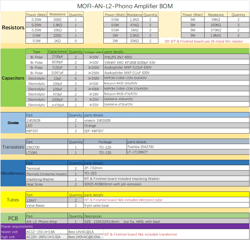
PCB SIZE: 153X152X1.6mm 1oz Cu, HASL with lead.
Power requirements:
heater volt: AC12~15V, I≥0.8A, Best: 14VAC@1A;
high volt: AC100~260V, I≥0.02A, Best:120VAC@0.1A.
Product configuration
DIY kit: Contains the PCB and the components needed on the PCB, but does not include the power transformer and the electronic tube.
Finished board: Based on the well-tested board on the standard version kit, we verified all key points' voltage, and used the signal generator and oscilloscope for analog waveform double verification. We will not use this board for listening test.
All finished pcbs are all carefully hand-soldered and fully tests, so the price is higher and less cost performance. Price-sensitive consumers but with have DIY ability are recommended to choose the kit.
Schematic & key point of debugging
PCB comes with component parameters for easy installation.
We only refer the schematic of the amplification part of the circuit. If you need full circuit parameter, please read the component value with the PCB by yourself; we do not provide additionally.
please keep test point voltage close enough to it, +-20% is also permitted.


DIY KIT Instructions
Since the PCB holes are plated through, you only need to solder the parts from the bottom of the board. Do not drill or enlarge the holes because that would damage the through-plating.
Clean both sides of the blank PCB with paper towel and isopropyl alcohol or electronics flux remover, then solder the components to the board, starting with the lowest profile parts. This means the resistors and zener diode. Then solder the small capacitors, small transistors, followed by the larger capacitors.
Make sure the correct part goes into each position on the circuit board. Measure each resistor with your multimeter to ensure it's the proper value.
Pay attention to the polarity of electrolytic capacitors, diodes, , transistors as well as the orientation.
Clean up the solder flux residue from the board with isopropyl alcohol (or electronics flux remover) and a brush.
Inspect all solder connections carefully, using a magnifying glass, to make sure there are no solder bridges or cold solder joints. Use a multimeter in ohms scale to check for short circuits.
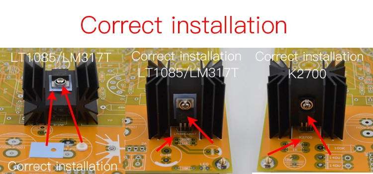
Since each LT1085/LM317T's mounting tab is internally connected to the pin2, it will carry live voltages and should not be shorted to the chassis, ground or other parts of the circuit.
The K2700 are vulnerable to electrostatic discharge damage when you are handling them, so keep their pins plugged into anti-static foam while working with them until you're ready to solder them to the board. Set the heatsinks pre-mounted with the K2700 aside for now.
Parts list
Pics
DIY KIT

Pics
Finished board


