
Voltage: DC 5V
Current: 40mA
Support: read EM / ID 125kHz and S50 / S70 IC 13.56MHz cards
Support: read EM / ID 125kHz and S50 / S70 IC 13.56MHz cards
Interface: Wiegand, UART
UART module with 3pin cable,
WG module with 5 pin cable.
UART board only. If WG format is required, Please weld the wire yourself.
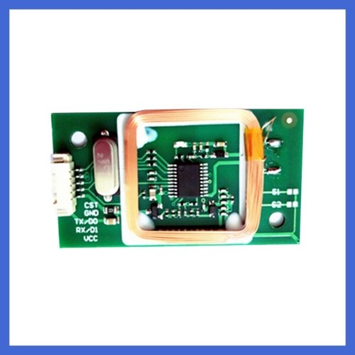
Interface Description:
5v D1 D0/TXD GND CST
Power supply: DC 5V power supply, choose linear power supply can get better card reading effect
D1: WG outputs data1, Data0
The pin of Data0 or UART module output by d0 / TXD WG is the serial port data output terminal
CST: W26 / 34 format selection (hanging means W26, grounding means W34) also has other functions
Introduction to Wiegand interface output:
1. When a card is sensed, the serial number of the card will be output through Data0 and data1.
2. Data0 and data1 are both high level without data output.
3. Data bit 0: a 400 US wide low level is generated on the Data0 line.
4. Data bit 1: generate a 400us wide low level on data1 line.
5. The length of each bit of data is 2400us
6. Each Mifare card has a 4-byte serial number. We output the last three bytes.
7. Add the first 12 bit even parity check bit in the front, and add the last 12 bit odd parity bit after it, with a total of 26 bits of data.
8. Card number: 6B 3D 12 D6
9. Output data: 3D 12 D6
Weigand 26 :
0 | 00111101 | 00010010 | 11010110 | 1 |
even parity | 3D | 12 | D6 | Odd parity |
Weigand 34 :
0 | 01101011 | 00111101 | 00010010 | 11010110 | 0 |
even parity | 6B | 3D | 12 | D6 | Odd parity |
Baud rate:9600
Start data | length | Card type | Card data | BCC check | End of data |
0x02 | 0x09 | 0x01 | SN0~SN3 | Exclusive or operations other than the beginning and end of data | 0x03 |
Among them, the card types are:
0x02 EM4100
0x01 MIFARE 1K
For example, the data received by the serial port tool is 02 09 02 04 2E 53 82 F03
The first byte, 0x02, indicates the beginning of the data.
The second byte, 0x09, indicates that the whole data length is 9 bytes, including data start and data end.
The third byte, 0x02, indicates that the card type is em4100.
The fourth byte to the seventh byte (0x04 0x2e 0x53 0x82) indicates the card number read.
The 8th byte, 0xf0, represents the BCC check from the 2nd byte to the 8th byte.
The ninth byte, 0x03, indicates the end of the data.
Package:
1x rfid reader module with 5pin cable(WG26/34)
or
1x rfid reader module with 3pin cable(UART )