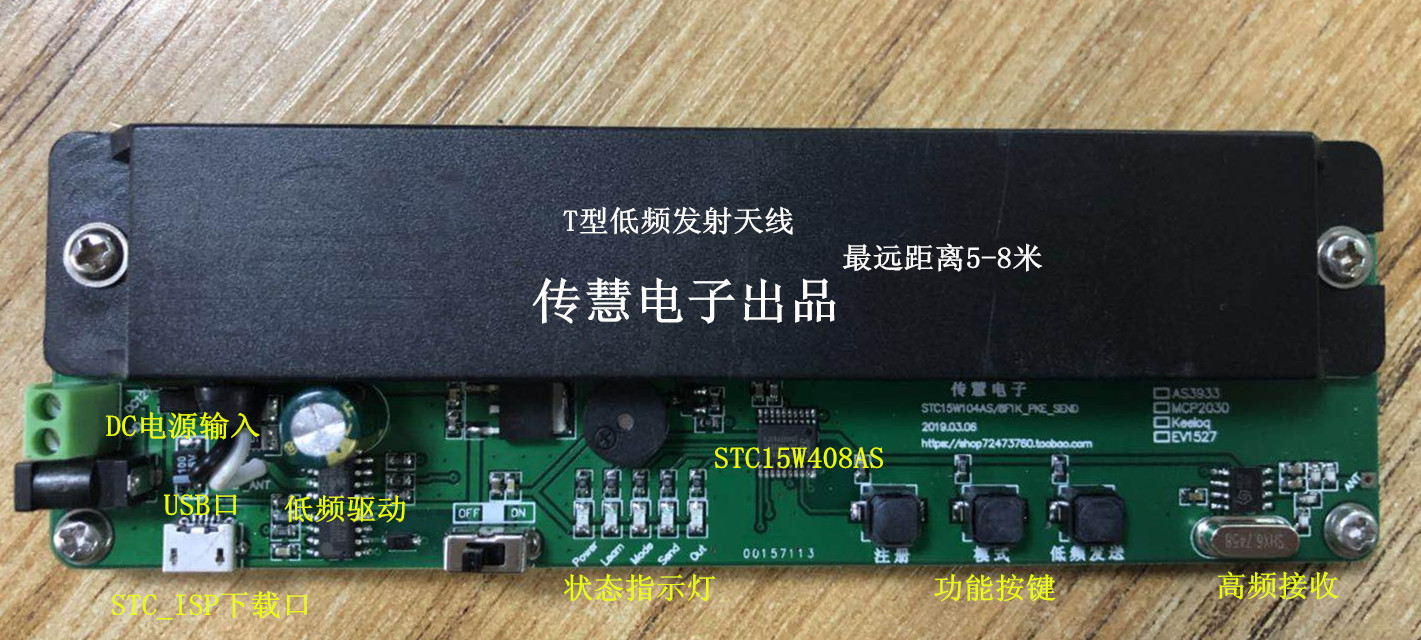
New board
1. MCU model: STC15W404AS / STC8A2K16S2, internal 32M.
2.433Mhz superheterodyne receiving module: SYN480.
3. Low frequency wakes up the transmitting antenna.
4. Low-frequency wake-up antenna voltage selection: DC 5 / 12V.
5. Onboard USB to TTL, to achieve communication, download programs, power supply.
6. Wake distance 1-8m
Remote end:
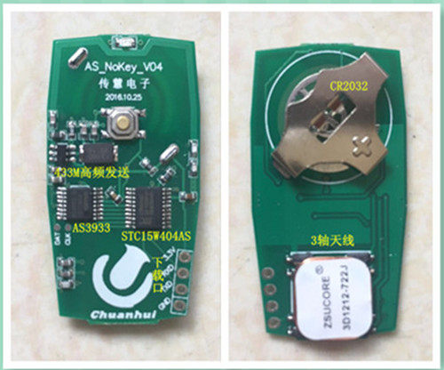
1. MCU model: STC15W404AS / STC8A2K16S2 internal 11.0592M.
2.433Mhz sending module: SYN113 / 115.
3. Low frequency wakes up the receiving antenna in the x / y / z direction.
4. Remote control buttons.
5. Download and communication interface (pad type).
6. CR2032 button battery (seat), the courier is not required to send batteries.
7. Wake distance 1-8m
8. Standby power consumption 6ua.
Base station configuration software:
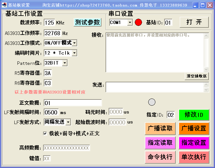
You can directly operate the host computer to design the working parameters of the base station. After setting the parameters, click Execute to send the input parameters to the base station board. The base station board saves the parameters to the AT24C02. The configuration parameters inside the base station can also be read out.
Operating procedures:
1. Install the CR2032 battery on the base station board, and connect the sending board with the Android mobile phone data cable to the computer (or plug in the DC12V power supply).
2. The ideal position of the receiving board antenna is parallel to the receiving antenna (the farthest distance).
3. Turn on the power switch, the base station board is powered on, and the base station board starts to send a wake-up signal (the base station board 433 RF is ready to receive the remote control board return data waiting time is about 4S, no data relay buzzer does not operate), when sending the LF wake-up signal The Study indicator lights up once, the STC MCU is awakened after receiving the wake-up signal from the remote control board, and at the same time, the HCS300 / 301 66bit fixed code (also can be customized or rolling code) data is sent continuously 3 times through the 433M RF transmission module MCU The data is decoded, after verifying the validity, the relay is turned on, the buzzer sounds a 1-3 sound, and the Study indicator lights.
4. Manual mode: The default automatic mode when the base station board is turned on (cyclically sending LF signals at intervals of 4S), press and hold the Auto_Key button, and then turn it on
The base station board power supply, after the buzzer sounds, let go and change the mode once. Manual mode and automatic mode switch. Manual mode
The LF signal will not be sent automatically in the mode, you need to short press the Auto_Key button, press once to send the LF signal once and wait
To receive high frequency data (wait for 4S).
5. Description: The reason why the base station board does not operate after the receiving board waits for 4S:
1). The receiving end is far away (the board is a test board, the actual effect of the high-frequency remote control is relatively poor, the non-commercial grade is only for testing, and is not used to evaluate the performance of the test board. For the actual use range, it is necessary to pay attention to the matching of the antenna resonance capacitance to further enhance the LF effect. There are 32PF step-by-step adjustable resonance capacitance inside the AS3933).
2). Whether the remote control is learned, re-learn again.
6. The general flow of control: the remote control board is awakened ---> after awakening, the analog code 433M is sent ---> the 433M receiving signal of the sending board ---> the base station board checks whether the received data is legal ----> turn on the relay Output, indicator, buzzer.
7. Detailed operation instructions. Please ask for a manual, which is slightly different from the above, but the general operation method is the same.
Shipping list:
1. One receiving board and one sending board.
2. CR2032 button battery (not sent by SF Express).
3.125Khz transmit antenna one.
4. Schematic diagram, PCB diagram, source code Send by e-mail, please remember to note the mailbox.
special attention items:
1. After receiving the test board, please test carefully. If the hardware is faulty or unsatisfactory, please contact the seller to solve it (return or change).
2. After you are satisfied with the trial, ask the seller for the development board schematic, PCB diagram, and source code. Once this information is sent, you will not accept any return requirements. Hope to understand! Be sure to consider carefully before sending information to avoid unnecessary losses to you.