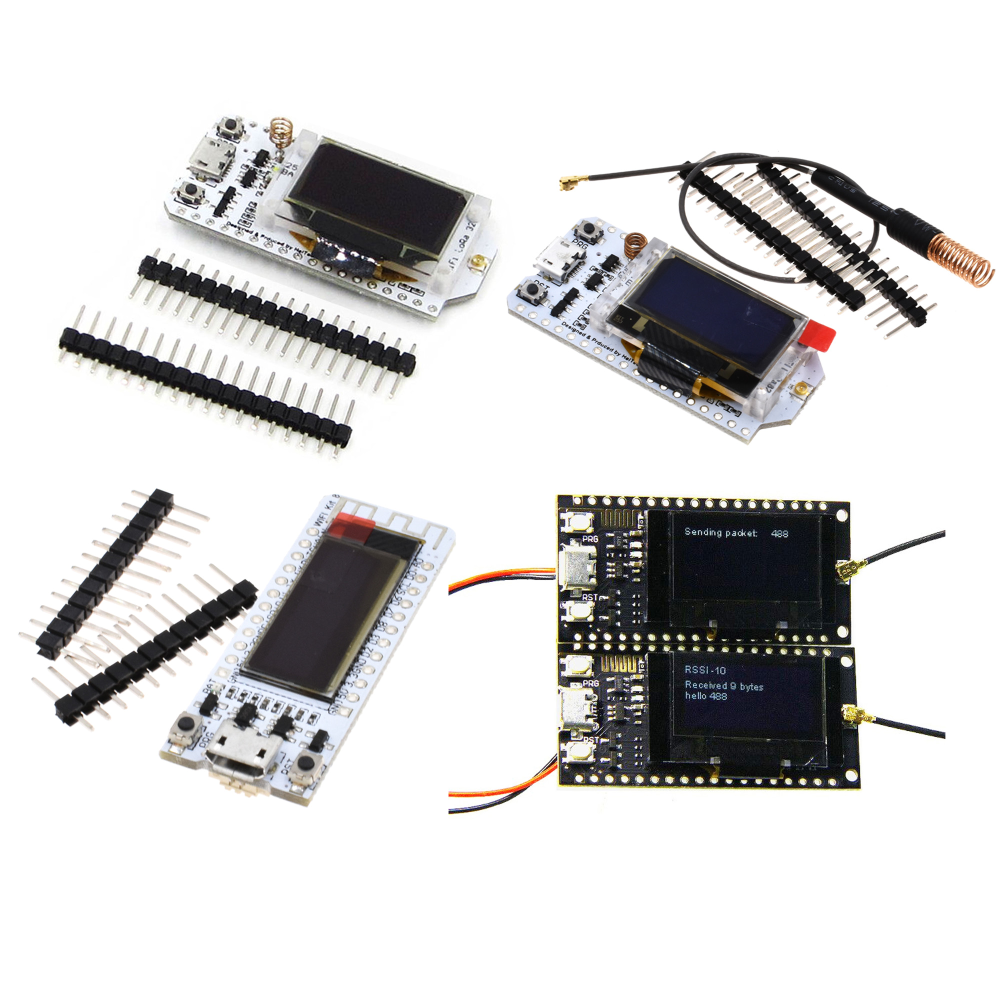
LORA SX1276 ESP32 OLED
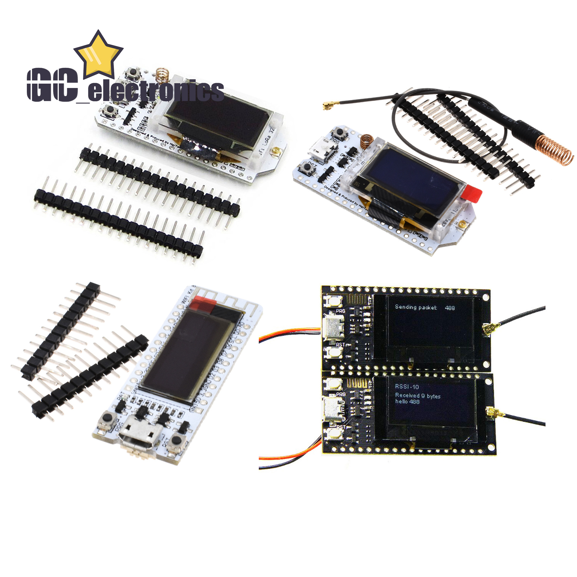
868MHz-915MHz SX1276 ESP32 LoRa 0.96 Inch Blue OLED Display Bluetooth WIFI Lora Kit 32 Module IOT Development Board for Arduino
If you need the document of this product,please contact us freely.
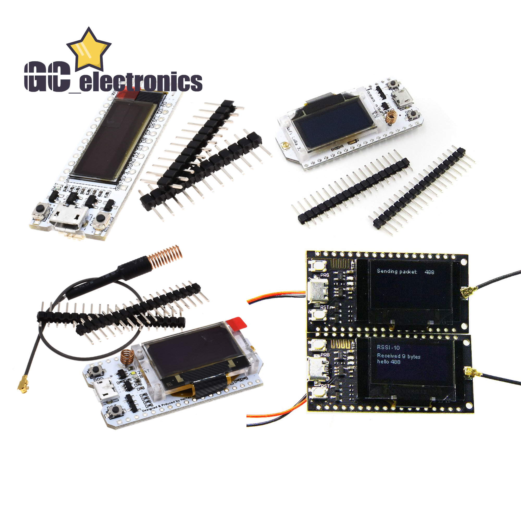
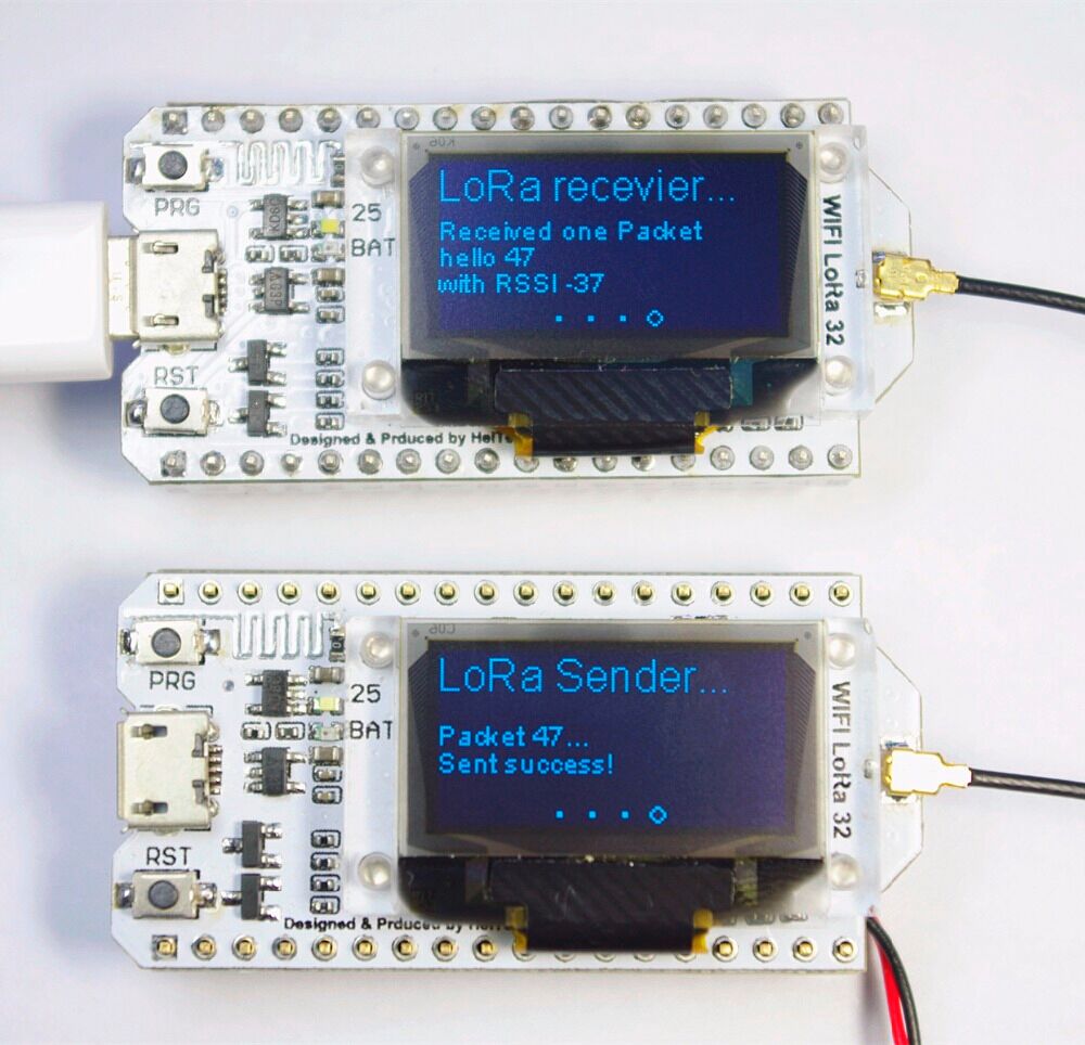
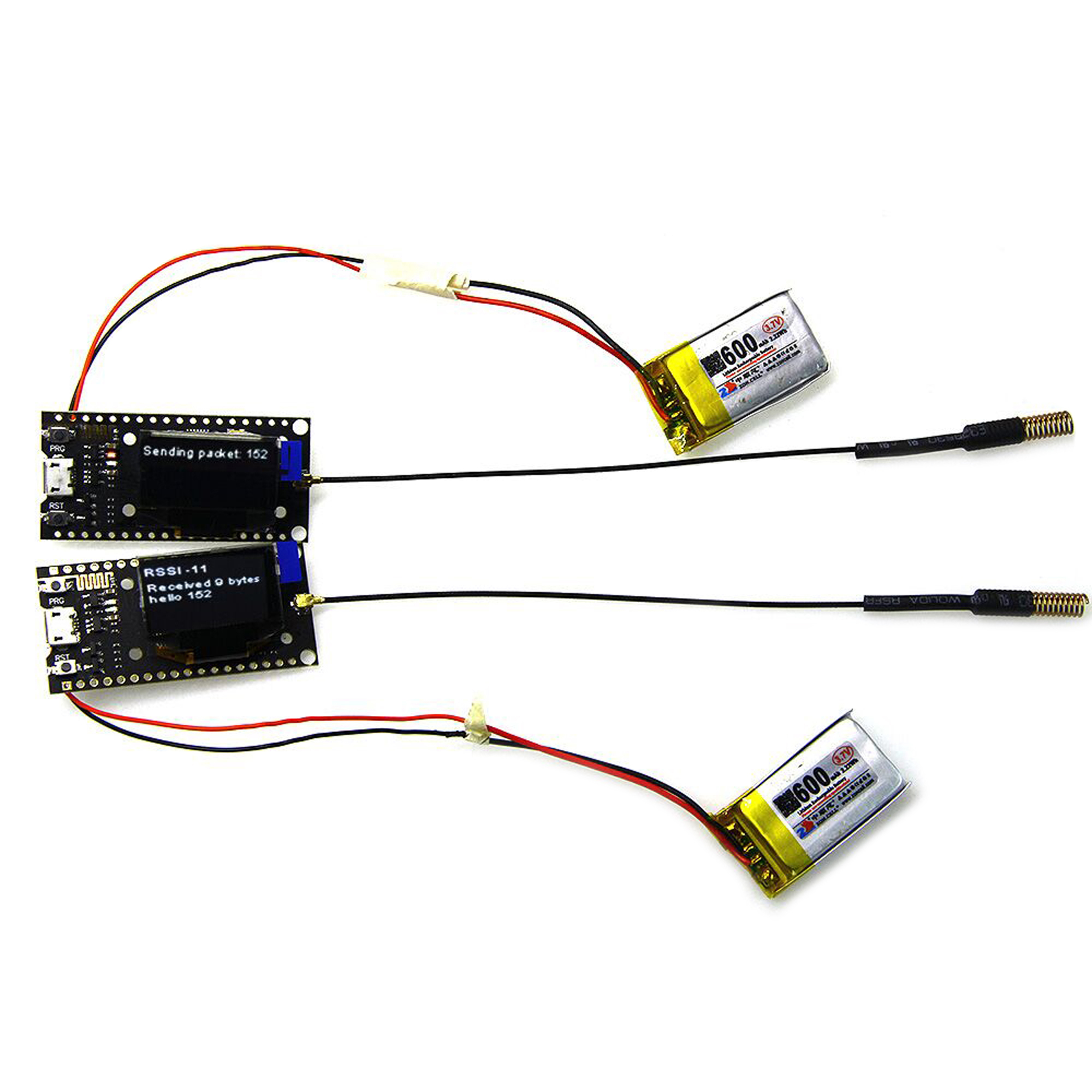
LoRa send and receive test
WIFI Kit series is the new development of the cost-effective networking program, the main chip using ESP32, LX6 dual-core processor, computing power up to 600DMIPS, chip built-in 520 KB SRAM, 802.11 b / g / N HT40 Wi-Fi transceiver, baseband, protocol stack and LWIP, integrated dual-mode Bluetooth (traditional Bluetooth and BLE low power Bluetooth).
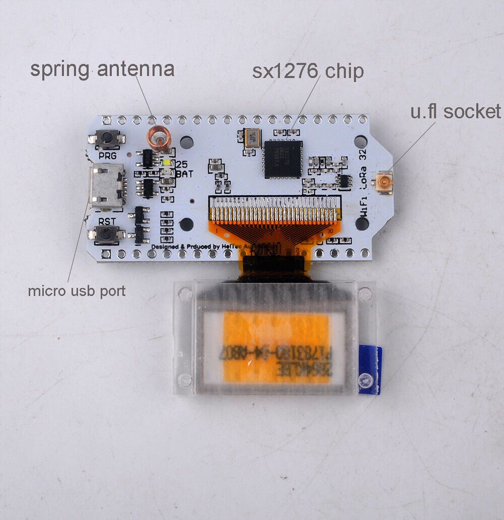
This product is based on the WIFI Kit 32 added SX1276 chip, that is, LoRa ™ remote modem, Applicable frequency:868MHz -915MHz frequency, about -148dBm high sensitivity, +20 dBm power output, high reliability, transmission distance (measured open area communication distance 2.6Km).
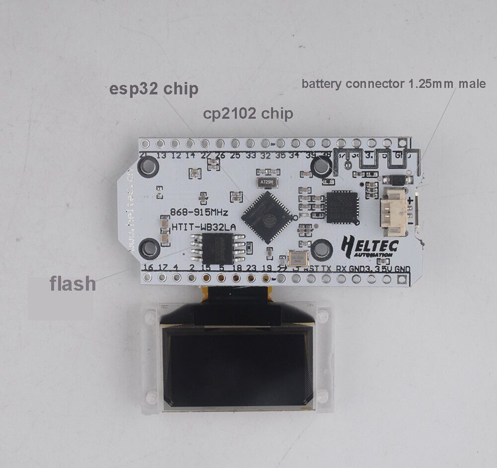
Onboard 32MByte Flash, Wi-Fi antenna, 0.96-inch blue OLED display, lithium battery charging circuit and interface, CP2102 USB to serial chip, the perfect support for Arduino development environment, can be very simple and fast for program verification and product development.
Technical Parameters:
Flash: 32M-Bits
Processor: for Tensilica LX6 Dual Core
Master chip: ESP32
LoRa chip: SX1276
Support frequency band: 868-915MHZ
Open communication distance: 2.8KM
Computing capacity: up to 600DMIPS
Dual-mode Bluetooth: traditional Bluetooth and BLE low-power Bluetooth
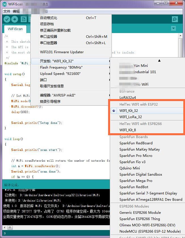
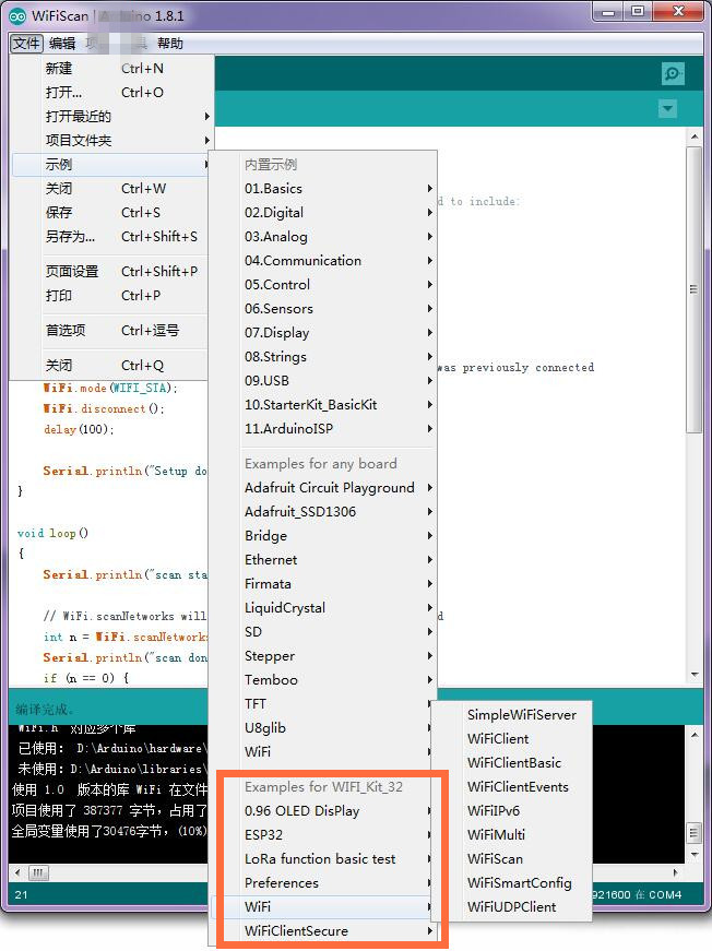
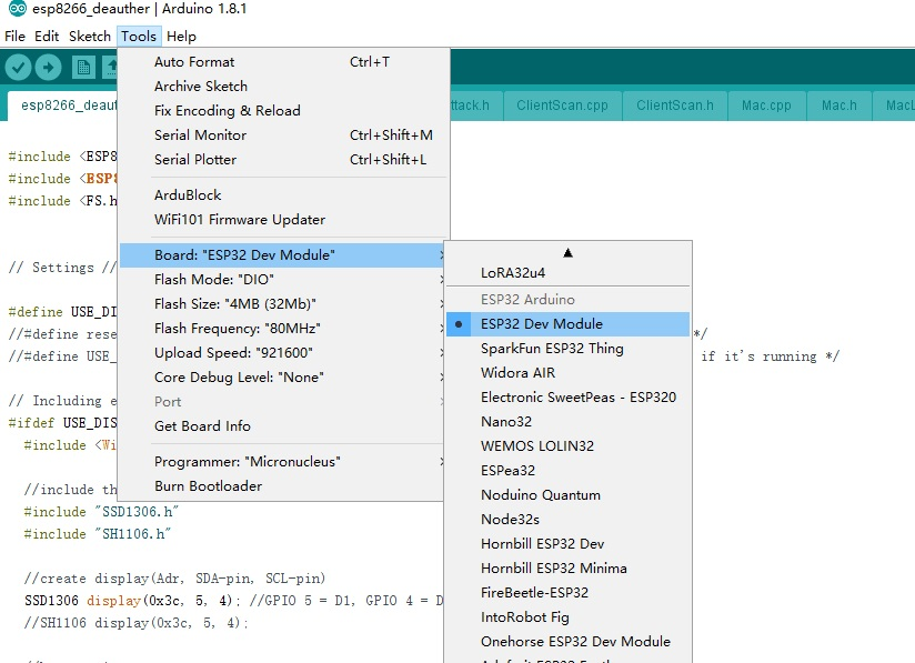
Development environment: perfect support for Arduino
Operating voltage: 3.3-7V
Operating temperature range: -40-90 ℃
Receiver sensitivity: -139dBm (SF12, 125KHZ)
UDP continuous throughput: 135Mbps
USB adapter chip: CP2102
Support mode: Sniffer, Station, softAP and Wi-Fi Direct
Transmit power: 19.5dBm@11b, 16.5dBm@11g, 15.5dBm@11n
Data rate: 150Mbps @ 11n HT40, 72Mbps @ 11n HT20,
54Mbps @ 11g, 11Mbps @ 11b
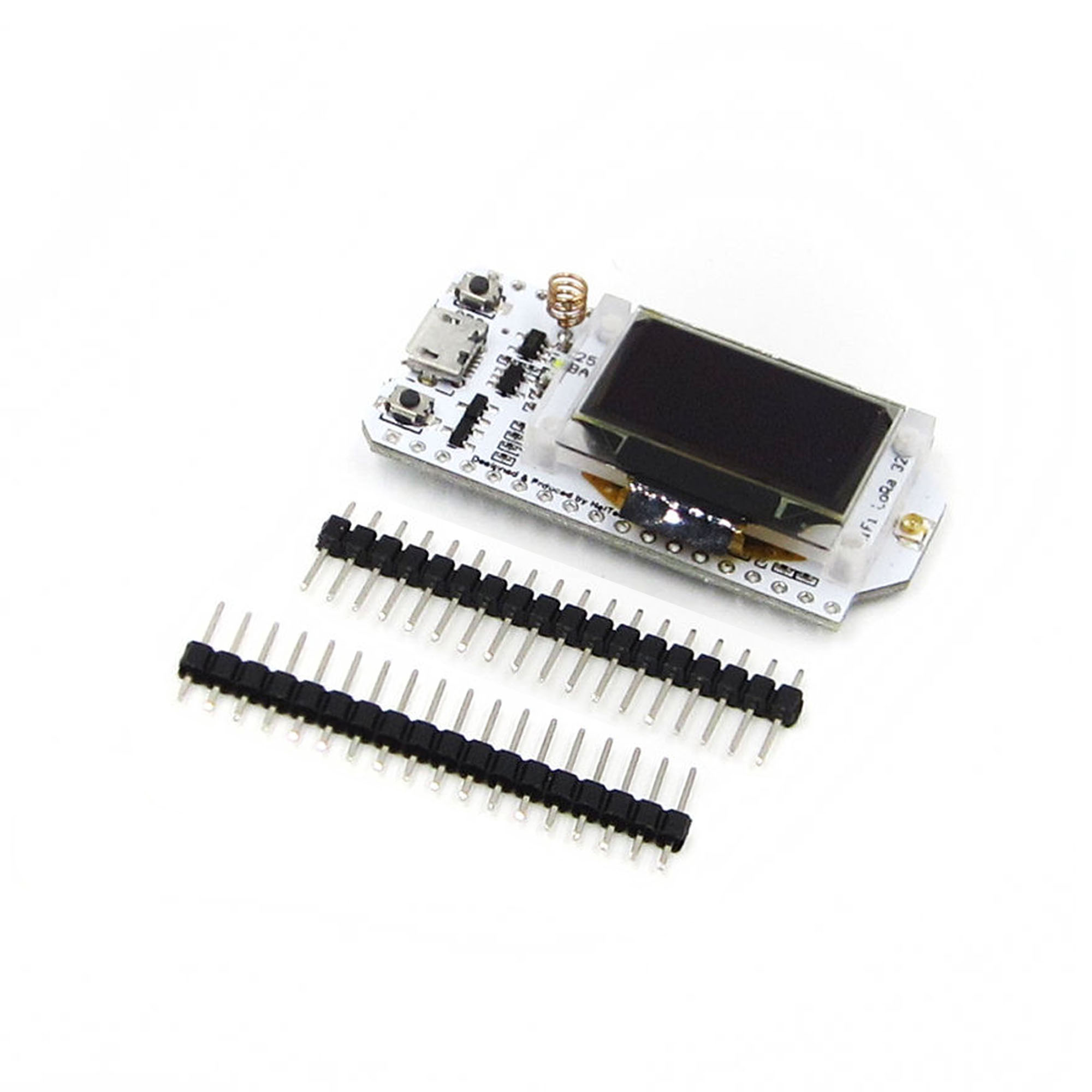
Package Includes:
1 X ESP32 Lora OLED development board
2 X Pin header
2 X Pin header stickers
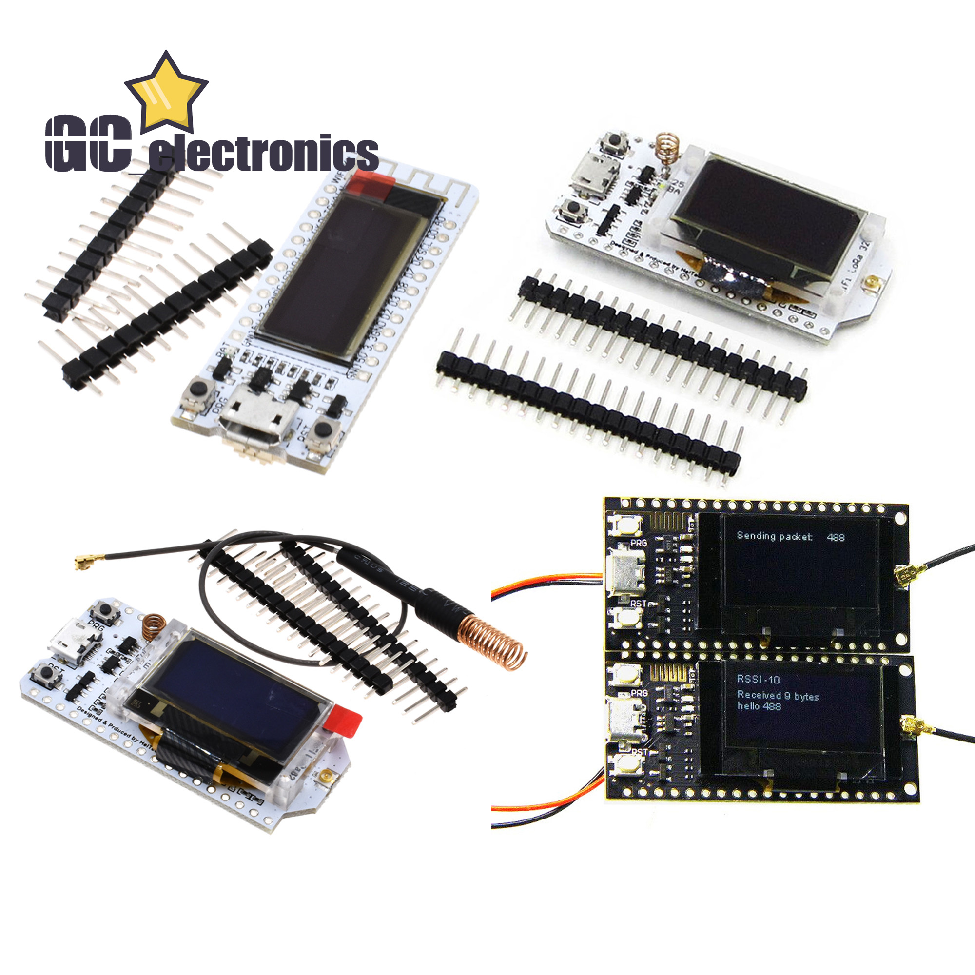
LORA SX1278 433Mhz
The 433MHz antenna must be used in conjunction with the IPEX interface (if the
antenna is not connected, it may damage the LoRa chip)Lithium battery charging
and discharging circuit, when the battery is full, the blue LED will stop working.
When using, pay attention to the positive and negative of the battery, otherwise
it will be damaged!
Using the IO port touch screen touch signal input, you need to add the 100nF
pull-down capacitor at this pin!
Example:
This product is a SX1278 chip based on ESP32(revision 1) WIFI increased OLED, namely LoRa
remote modem, 433MHz frequency, high sensitivity is about -148dBm, +20dBm output
power, high reliability, long transmission distance.
The onboard 16 Mt bytes (128 Mt ), Wi-Fi antenna, 0.96 inch blue OLED display, lithium battery
charging circuit, CP2102 interface and USB serial chip, the perfect support for Arduino
development environment, can be used for program verification and product development
is very simple and fast.
Operating voltage: 3.3V to 7V
Operating temperature range: -40 degrees C to +90 degrees C
Support for Sniffer, Station, softAP, and Wi-Fi Direct modes
Data rates: 150 Mbps@11n HT40, 72 Mbps@11n HT20, 54 Mbps@11g, 11 Mbps@11b
Transmit power: 19.5 dBm@11b, 16.5 dBm@11g, 15.5 dBm@11n
Receiver sensitivity up to -98 dBm
UDP sustained throughput of 135 Mbps
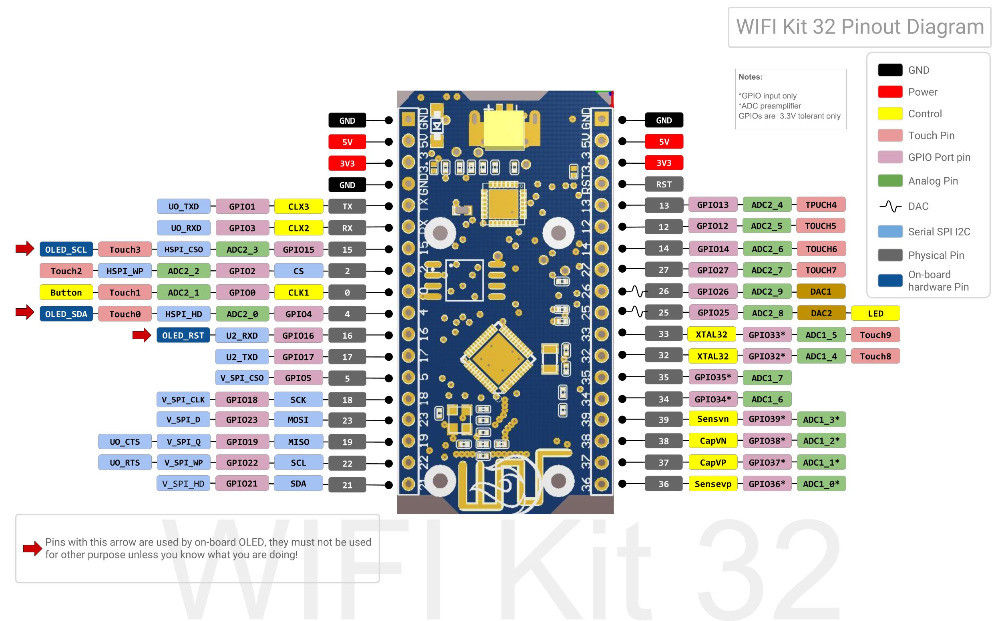
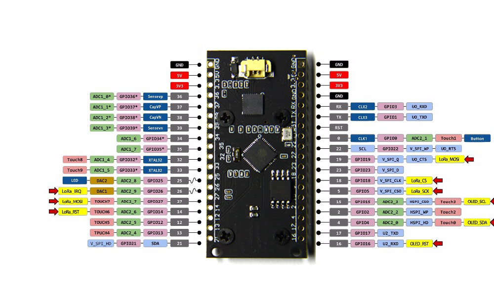
Pin reference description
Test details
For example One
(1)LoRaSender
#include <SPI.h>
#include <LoRa.h>
#include<Arduino.h>
// GPIO5 -- SX1278's SCK
// GPIO19 -- SX1278's MISO
// GPIO27 -- SX1278's MOSI
// GPIO18 -- SX1278's CS
// GPIO14 -- SX1278's RESET
// GPIO26 -- SX1278's IRQ(Interrupt Request)
#define SS 18
#define RST 14
#define DI0 26
#define BAND 433E6
int counter = 0;
void setup() {
pinMode(25,OUTPUT); //Send success, LED will bright 1 second
Serial.begin(115200);
while (!Serial); //If just the the basic function, must connect to a computer
SPI.begin(5,19,27,18);
LoRa.setPins(SS,RST,DI0);
// Serial.println("LoRa Sender");
if (!LoRa.begin(BAND)) {
Serial.println("Starting LoRa failed!");
while (1);
}
Serial.println("LoRa Initial OK!");
}
void loop() {
Serial.print("Sending packet: ");
Serial.println(counter);
// send packet
LoRa.beginPacket();
LoRa.print("hello ");
LoRa.print(counter);
LoRa.endPacket();
counter++;
digitalWrite(25, HIGH); // turn the LED on (HIGH is the voltage level)
delay(1000); // wait for a second
digitalWrite(25, LOW); // turn the LED off by making the voltage LOW
delay(1000); // wait for a second
delay(3000);
}
For example Two
(2)LoRaReceiver
#include <SPI.h>
#include <LoRa.h>
// GPIO5 -- SX1278's SCK
// GPIO19 -- SX1278's MISO
// GPIO27 -- SX1278's MOSI
// GPIO18 -- SX1278's CS
// GPIO14 -- SX1278's RESET
// GPIO26 -- SX1278's IRQ(Interrupt Request)
#define SS 18
#define RST 14
#define DI0 26
#define BAND 433E6
void setup() {
Serial.begin(115200);
while (!Serial); //if just the the basic function, must connect to a computer
delay(1000);
Serial.println("LoRa Receiver");
SPI.begin(5,19,27,18);
LoRa.setPins(SS,RST,DI0);
if (!LoRa.begin(BAND)) {
Serial.println("Starting LoRa failed!");
while (1);
}
}
void loop() {
// try to parse packet
int packetSize = LoRa.parsePacket();
if (packetSize) {
// received a packet
Serial.print("Received packet '");
// read packet
while (LoRa.available()) {
Serial.print((char)LoRa.read());
}
// print RSSI of packet
Serial.print("' with RSSI ");
Serial.println(LoRa.packetRssi());
}
}
For example three
(3)LoRaReceiverCallback
#include <SPI.h>
#include <LoRa.h>
// GPIO5 -- SX1278's SCK
// GPIO19 -- SX1278's MISO
// GPIO27 -- SX1278's MOSI
// GPIO18 -- SX1278's CS
// GPIO14 -- SX1278's RESET
// GPIO26 -- SX1278's IRQ(Interrupt Request)
#define SS 18
#define RST 14
#define DI0 26
#define BAND 433E6
void setup() {
Serial.begin(115200);
while (!Serial); //if just the the basic function, must connect to a computer
SPI.begin(5,19,27,18);
LoRa.setPins(SS,RST,DI0);
Serial.println("LoRa Receiver Callback");
if (!LoRa.begin(BAND)) {
Serial.println("Starting LoRa failed!");
while (1);
}
// register the receive callback
LoRa.onReceive(onReceive);
// put the radio into receive mode
LoRa.receive();
}
void loop() {
// do nothing
}
void onReceive(int packetSize) {
// received a packet
Serial.print("Received packet '");
// read packet
for (int i = 0; i < packetSize; i++) {
Serial.print((char)LoRa.read());
}
// print RSSI of packet
Serial.print("' with RSSI ");
Serial.println(LoRa.packetRssi());
}
For example four
#include <Wire.h> // Only needed for Arduino 1.6.5 and earlier
#include "SSD1306.h" // alias for `#include "SSD1306Wire.h"`
#include "images.h"
//OLED pins to ESP32 0.96OLEDGPIOs via this connecthin:
//OLED_SDA -- GPIO4
//OLED_SCL -- GPIO15
//OLED_RST -- GPIO16
SSD1306 display(0x3c, 4, 15);
#define DEMO_DURATION 3000
typedef void (*Demo)(void);
int demoMode = 0;
int counter = 1;
void setup() {
pinMode(16,OUTPUT);
digitalWrite(16, LOW); // set GPIO16 low to reset OLED
delay(50);
digitalWrite(16, HIGH); // while OLED is running, must set GPIO16 in high
Serial.begin(115200);
Serial.println();
Serial.println();
// Initialising the UI will init the display too.
display.init();
display.flipScreenVertically();
display.setFont(ArialMT_Plain_10);
}
void drawFontFaceDemo() {
// Font Demo1
// create more fonts at http://oleddisplay.squix.ch/
display.setTextAlignment(TEXT_ALIGN_LEFT);
display.setFont(ArialMT_Plain_10);
display.drawString(0, 0, "Hello world");
display.setFont(ArialMT_Plain_16);
display.drawString(0, 10, "Hello world");
display.setFont(ArialMT_Plain_24);
display.drawString(0, 26, "Hello world");
}
void drawTextFlowDemo() {
display.setFont(ArialMT_Plain_10);
display.setTextAlignment(TEXT_ALIGN_LEFT);
display.drawStringMaxWidth(0, 0, 128,
"Lorem ipsum\n dolor sit amet, consetetur sadipscing elitr, sed diam nonumy eirmod tempor invidunt ut labore." );
}
void drawTextAlignmentDemo() {
// Text alignment demo
display.setFont(ArialMT_Plain_10);
// The coordinates define the left starting point of the text
display.setTextAlignment(TEXT_ALIGN_LEFT);
display.drawString(0, 10, "Left aligned (0,10)");
// The coordinates define the center of the text
display.setTextAlignment(TEXT_ALIGN_CENTER);
display.drawString(64, 22, "Center aligned (64,22)");
// The coordinates define the right end of the text
display.setTextAlignment(TEXT_ALIGN_RIGHT);
display.drawString(128, 33, "Right aligned (128,33)");
}
void drawRectDemo() {
// Draw a pixel at given position
for (int i = 0; i < 10; i++) {
display.setPixel(i, i);
display.setPixel(10 - i, i);
}
display.drawRect(12, 12, 20, 20);
// Fill the rectangle
display.fillRect(14, 14, 17, 17);
// Draw a line horizontally
display.drawHorizontalLine(0, 40, 20);
// Draw a line horizontally
display.drawVerticalLine(40, 0, 20);
}
void drawCircleDemo() {
for (int i=1; i < 8; i++) {
display.setColor(WHITE);
display.drawCircle(32, 32, i*3);
if (i % 2 == 0) {
display.setColor(BLACK);
}
display.fillCircle(96, 32, 32 - i* 3);
}
}
void drawProgressBarDemo() {
int progress = (counter / 5) % 100;
// draw the progress bar
display.drawProgressBar(0, 32, 120, 10, progress);
// draw the percentage as String
display.setTextAlignment(TEXT_ALIGN_CENTER);
display.drawString(64, 15, String(progress) + "%");
}
void drawImageDemo() {
// on how to create xbm files
display.drawXbm(34, 14, WiFi_Logo_width, WiFi_Logo_height, WiFi_Logo_bits);
}
Demo demos[] = {drawFontFaceDemo, drawTextFlowDemo, drawTextAlignmentDemo, drawRectDemo, drawCircleDemo, drawProgressBarDemo, drawImageDemo};
int demoLength = (sizeof(demos) / sizeof(Demo));
long timeSinceLastModeSwitch = 0;
void loop() {
// clear the display
display.clear();
// draw the current demo method
demos[demoMode]();
display.setTextAlignment(TEXT_ALIGN_RIGHT);
display.drawString(10, 128, String(millis()));
// write the buffer to the display
display.display();
if (millis() - timeSinceLastModeSwitch > DEMO_DURATION) {
demoMode = (demoMode + 1) % demoLength;
timeSinceLastModeSwitch = millis();
}
counter++;
delay(10);
}
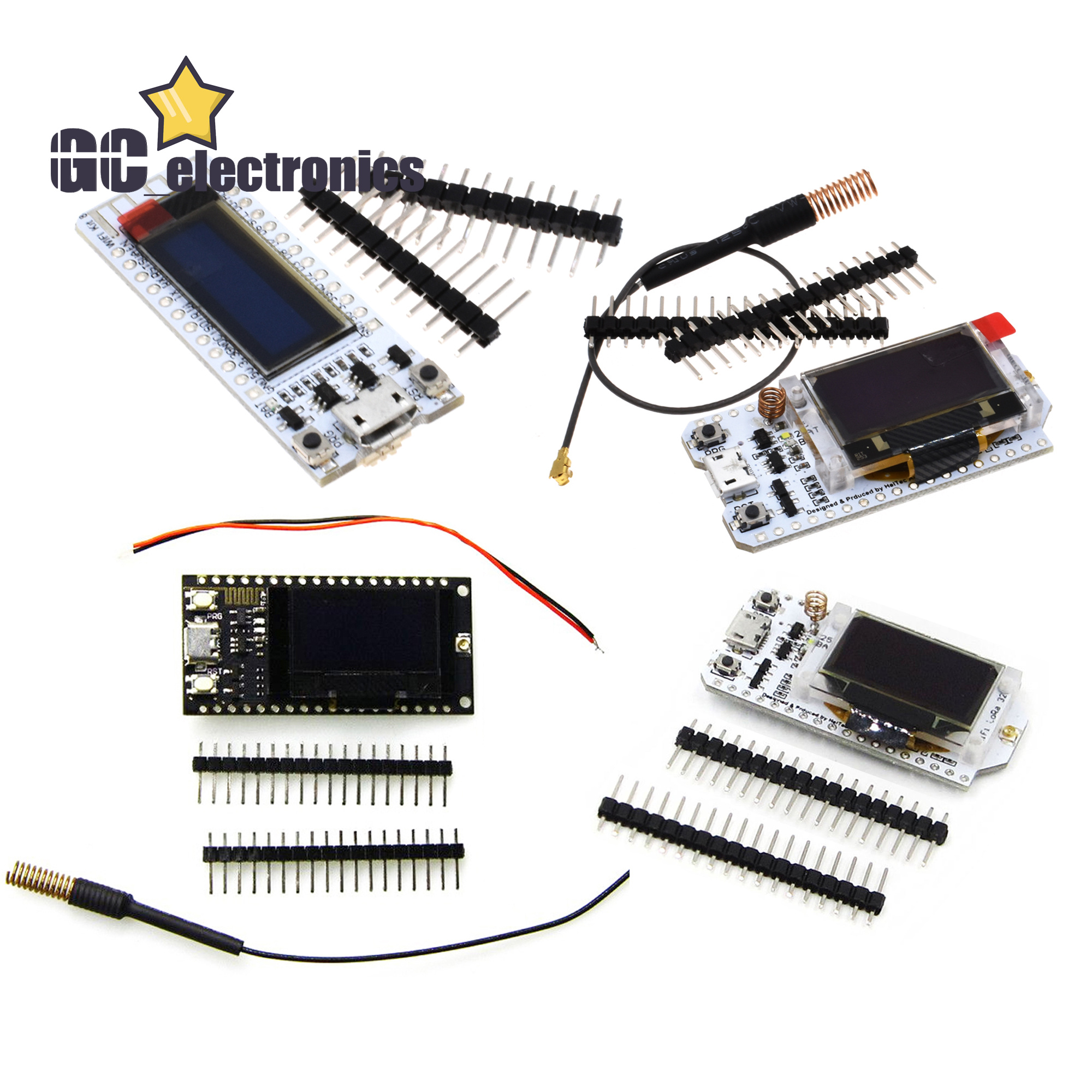
Note:This product does not include the battery.
shipping list:
ESP32(revision 1) OLED *1
Line *1
pin*2
433m Spring Antenna*1
LORA ESP32-S3FN8 SX1262 433Mhz
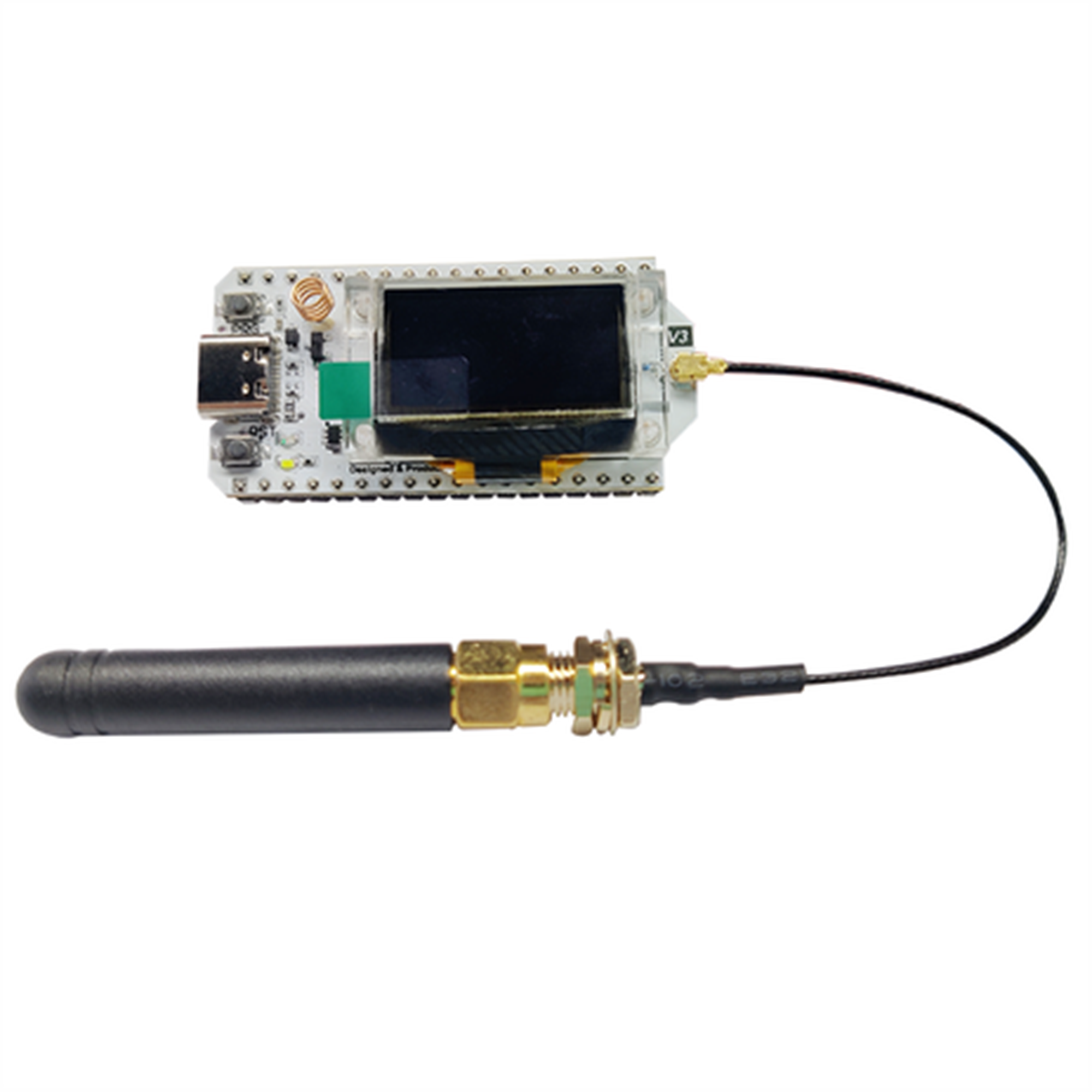
1.1 Overview
WiFi LoRa 32 is a classic IoT dev-board designed & produced by Heltec Automation.
Since its launch in 2017, it has been loved by developers and makers. The newly
launched V3 version has the same pin sequence as the V2 version, and retains Wi-Fi,
BLE, LoRa, OLED display and other functions. On this basis, the V3 version has been
➢ Microprocessor: ESP32-S3FN8 (Xtensa® 32-bit LX7 dual core processor, five stage
pipeline rack Structure, main frequency up to 240 MHz).
➢ SX1262 LoRa node chip.
➢ Type-C USB interface with a complete voltage regulator, ESD protection, short
circuit protection, RF shielding, and other protection measures.
➢ Onboard SH1.25-2 battery interface, integrated lithium battery management
system (charge and discharge management, overcharge protection, battery power
detection, USB / battery power automatic switching).
➢ Integrated WiFi, LoRa, Bluetooth three network connections, onboard Wi-Fi,
Bluetooth dedicated 2.4GHz metal spring antenna, reserved IPEX (U.FL) interface
for LoRa use.
➢ Onboard 0.96-inch 128*64 dot matrix OLED display, which can be used to display
debugging information, battery power, and other information.
➢ Integrated CP2102 USB to serial port chip, convenient for program downloading,
debugging information printing.
➢ Support the Arduino development environment.
➢ We provide ESP32 + LoRaWAN protocol Arduino® library, this is a standard
LORA ESP8266 WIFI NodeMcu
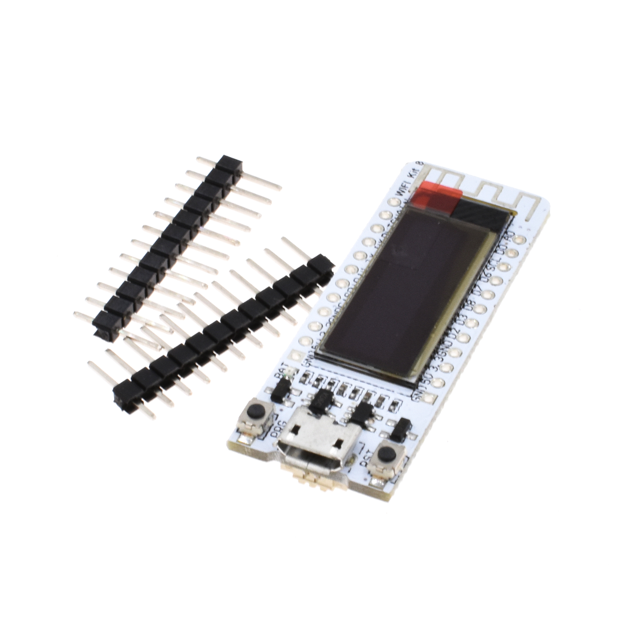
WIFI Kit 8 is developed by our company cost-effective Internet of things development program, the main chip using ESP8266, with CP2014USB to serial chip, lithium battery interface and charge and discharge circuit, 32MByte Flash, WIFI antenna, 0.91-inch OLED display.
Can be programmed in Ard uino and NodeMCU environments. Operation is consistent with NodeMCU.
Leads all pins of ESP8266
12 digital pins can be configured to read, write, IIC, SPI, the middle, PWM and other functions
1 AD input
Integrated 0.91-inch 128 * 32 OLED
Working voltage: 3.3V ~ 7V

On May 26, 2023 at 00:02:15 PDT, seller added the following information: