
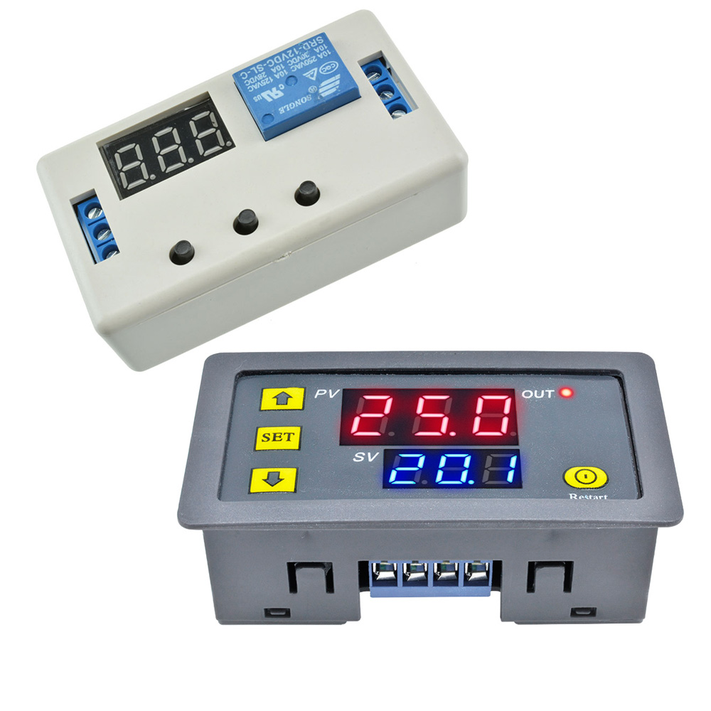
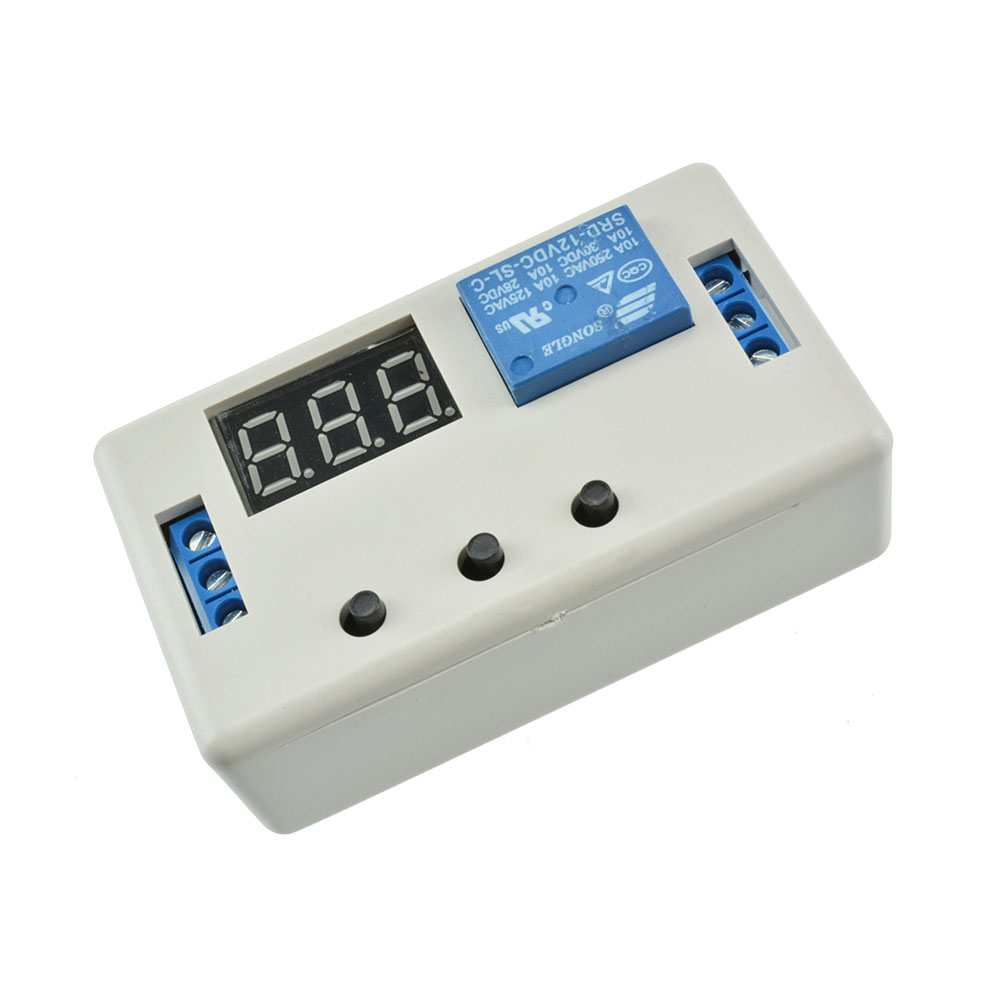

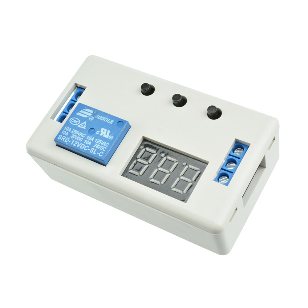
12V LED Automation Delay Timer Control Switch Relay Module with case
Description:
1. New upgrades to simplify,to meet customer needs.
2. Increase the supply anti-reversefunction.
3. The use of opto isolated input and output,enhanced anti-jamming capabilit
consumption.
4. Set parameter after power for ever memories.
5 . Signal terminal voltage signal can be maintained for a longtime.
6. to ensure stability,industrial grade board,class PLC.
Product parameters:
1. Size:64.2mm*34.8mm*18.5mm.
2. Relay Specifications:AC 220V 10A or DC 30V 10A.
3. Quiescent Current:20mA,Operating Current:50mA.
4. Working voltage:10~16V (if other ranges can be customized).
5. Signal voltage:4V~20V (if other ranges can be customized).
6. life:about100,000times,Working temperature:-40~85'C.
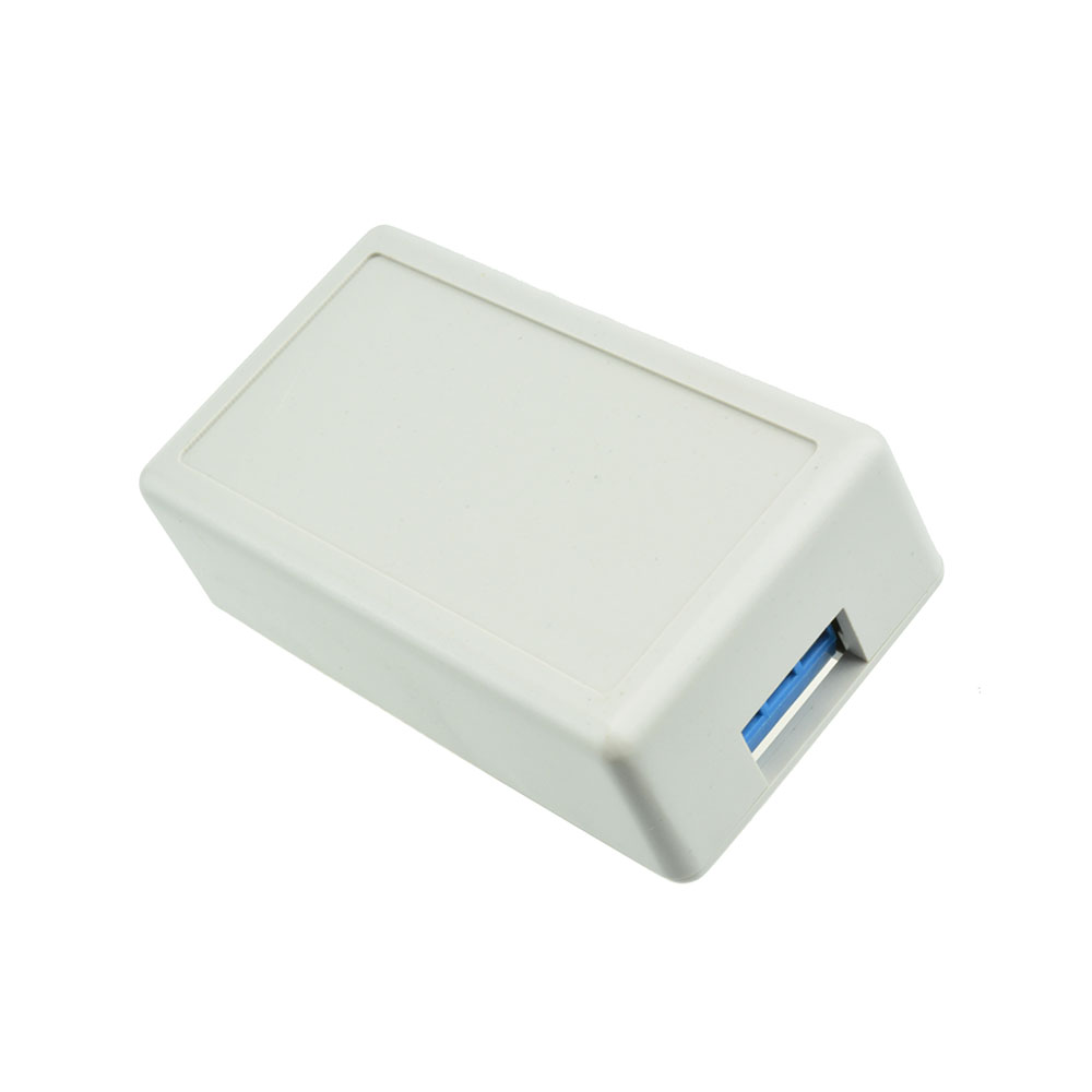
Package Included: 1PCS * 12V LED Automation Delay Timer Control Switch Relay Module PCB Board With Case
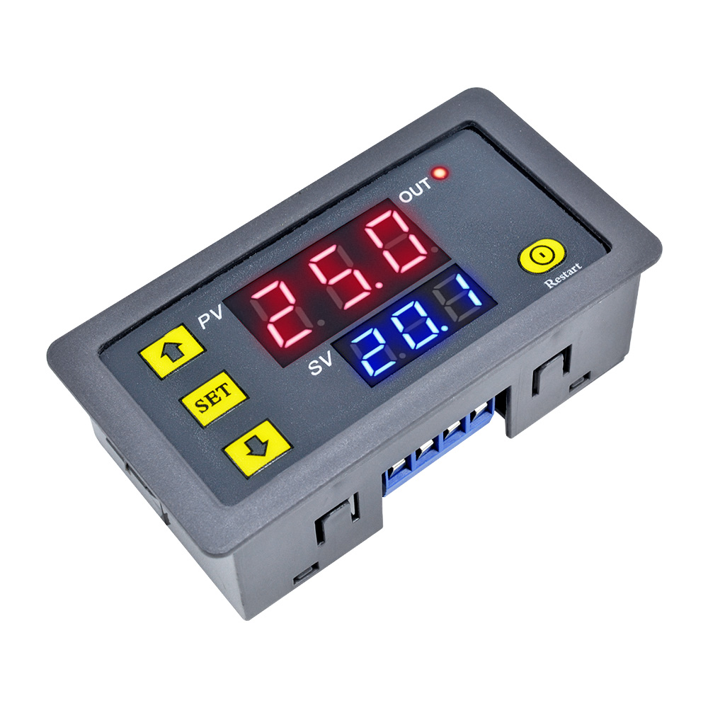
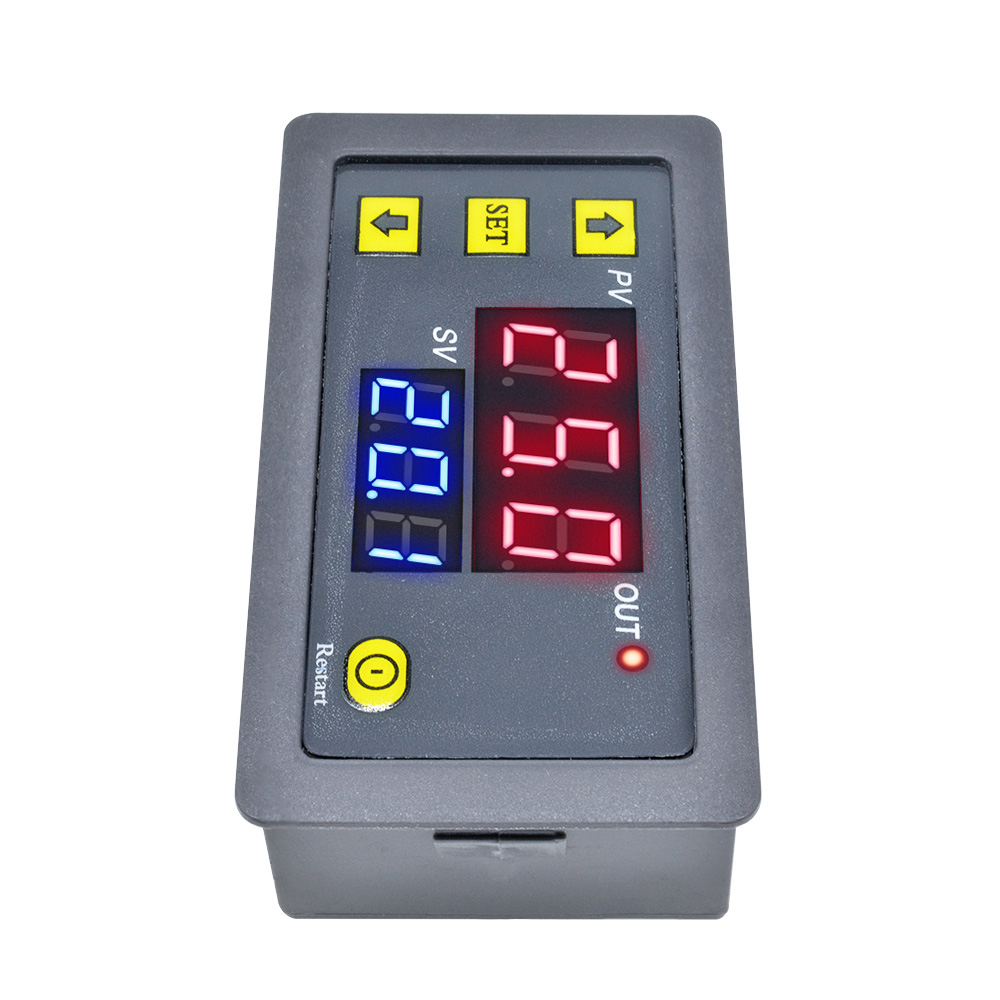
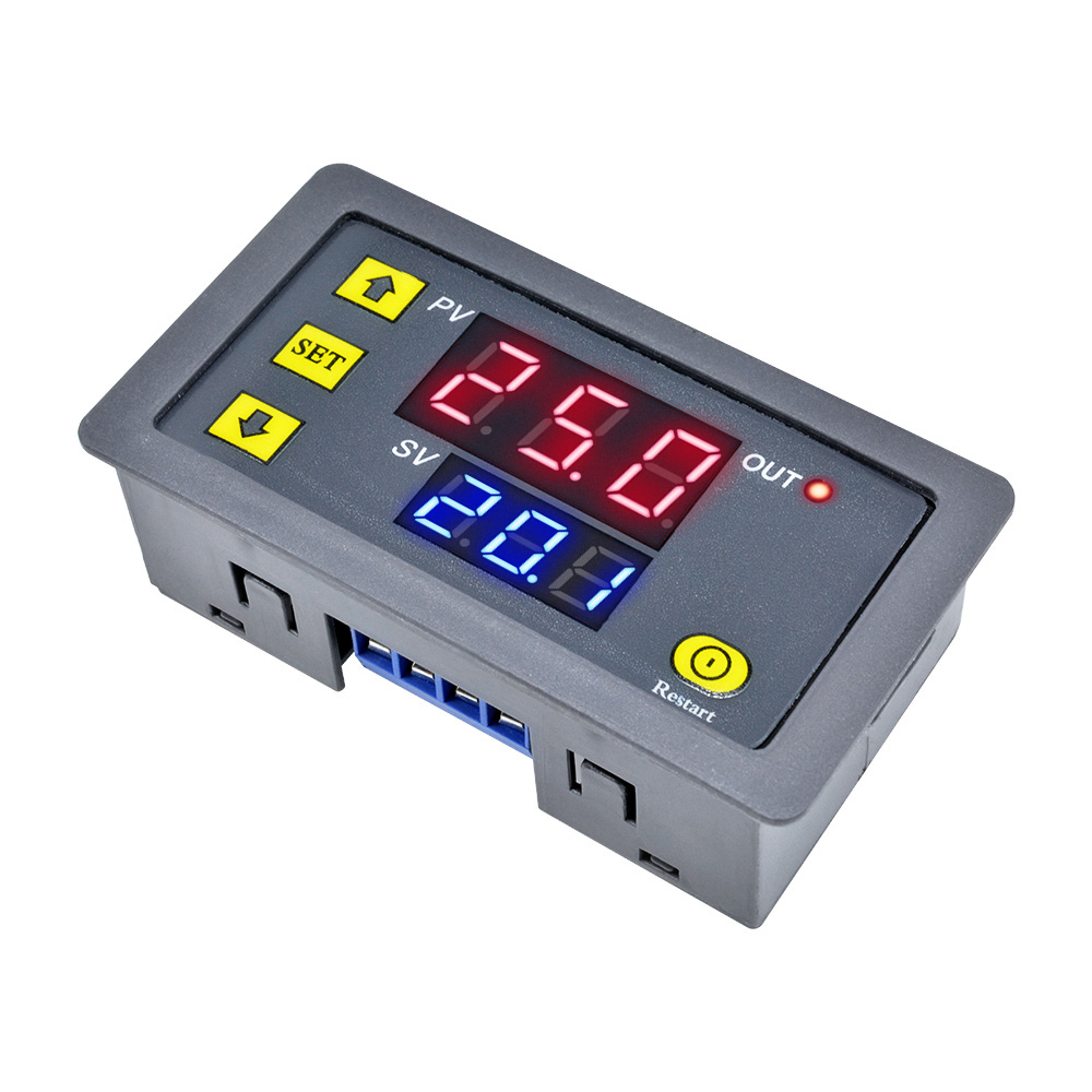
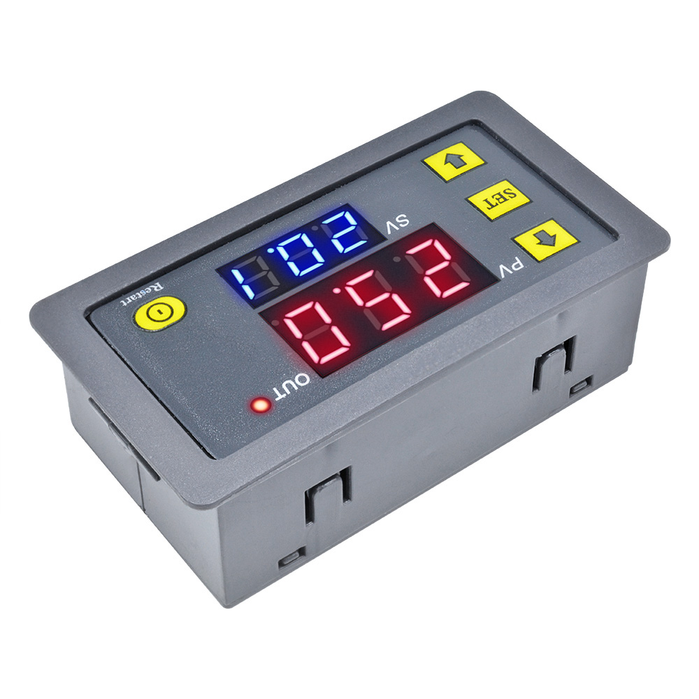
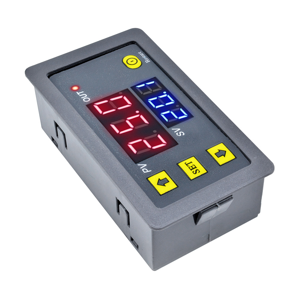
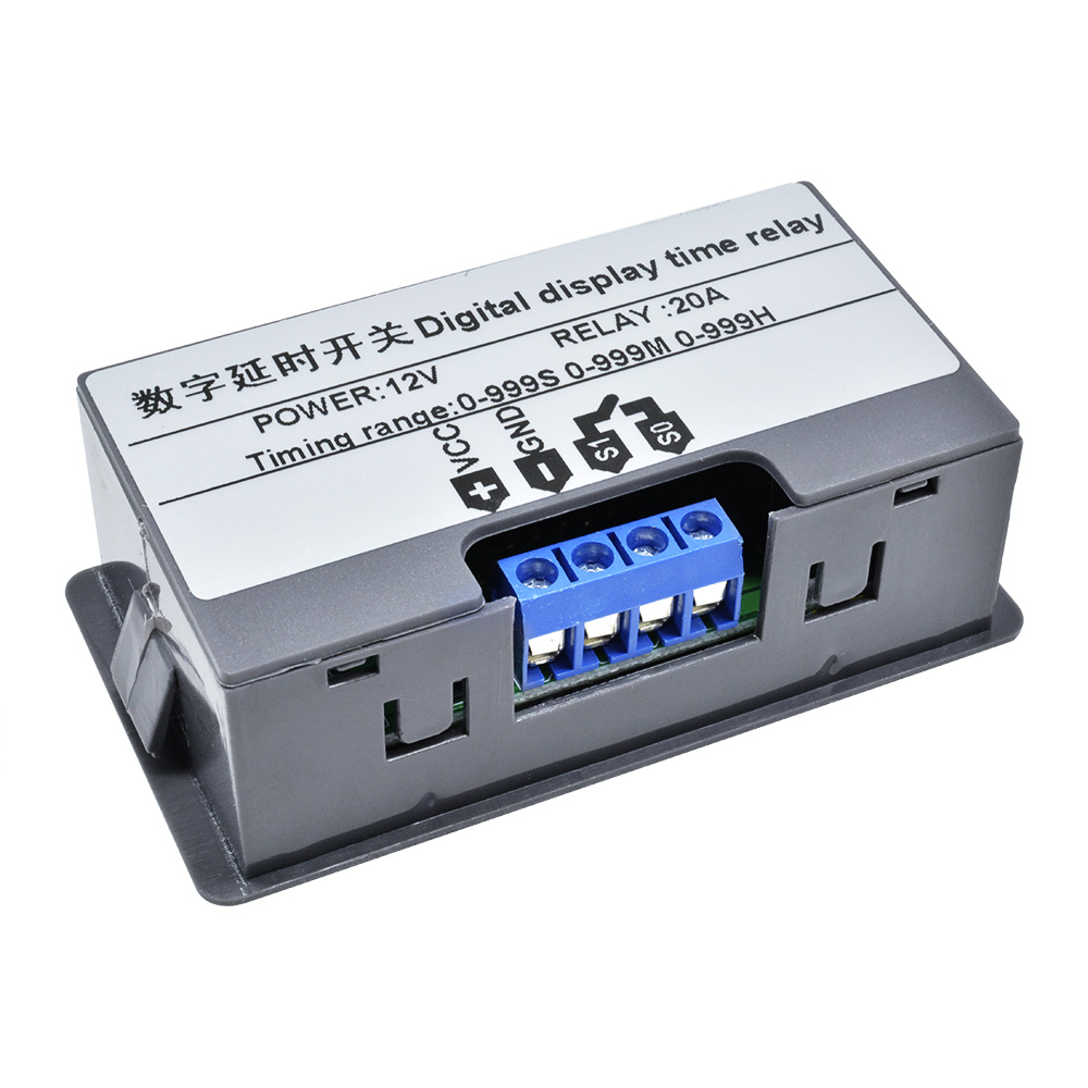
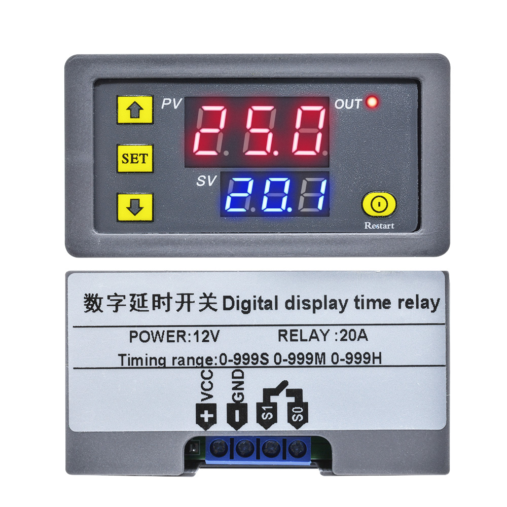
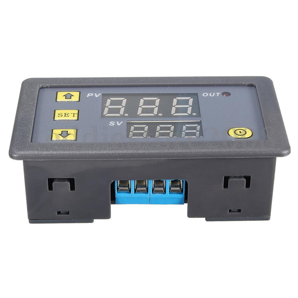
12V Cycle Timer Delay Dual Display Thermostat Relay Module
Timing range: 0-999 minutes 0-999 0-999 seconds when three kinds can select the desired
Dimensions: Display panel: 79mm * 43 installation: 71mm * 40mm24mm
Feature Sets: 18 kinds of combinations of features
Relay: Original 20A relays, power <1800W
System Power: 12v
Dimensions: Display panel: 79mm * 43 installation: 71mm * 40mm24mm
Feature Sets: 18 kinds of combinations of features
Relay: Original 20A relays, power <1800W
System Power: 12v
- Instruction Manual
Before using the first prompt the user to note that a certain set of data After waiting 6s, 6s after the memory module will automatically save the data set.
(1) Press SET key to enter the time setting mode, the digital tube flicker , buttons plus or minus buttons to adjust the timing T1 and the timing T2, after setting the time, must wait 5s, 5s after the module will automatically remember save data.
(2) Press SET, the parameter setting mode. There are two sets of parameters for the user to select P0, P1. In the current mode Short press SET to switch P0, P1. In P0, P1 parameter can be set for their own timer mode through the key addition and subtraction.
P0--0: timing mode is 0--999 ??seconds
P0--1: timing mode is 0--999 ??minutes
P0--2: timing when the pattern is 0--999
P1--0: T1 time delay relay (T1 timer)
P1--1: T1 delay time relay releases (T1 timer)
P1--2: time delay relay after T1 (T1 timer), then the delay time T2 successor electrical release (T2 timing) ends.
P1--3: T1 delay time relay releases (T1 timer), then the delay time T2 successor Electric energized (T2 timing) ends.
P1 --4: time delay relay after T1 (T1 timer), then the delay time T2 successor electrical release (T2 timer), repeat the cycle.
P1--5: T1 delay time relay releases (T1 timer), then the delay time T2 successor Electric energized (T2 timer), repeat the cycle.
Package includes: 1PCS 12V Timing Delay Relay Module Cycle Timer Digital LED Dual Display 0-999 hours