Language Switch
In the main interface, press 【F5 Diagnose】,then press 【F8 System definition】,then press 【F6
Language】, it will select needed language interface.
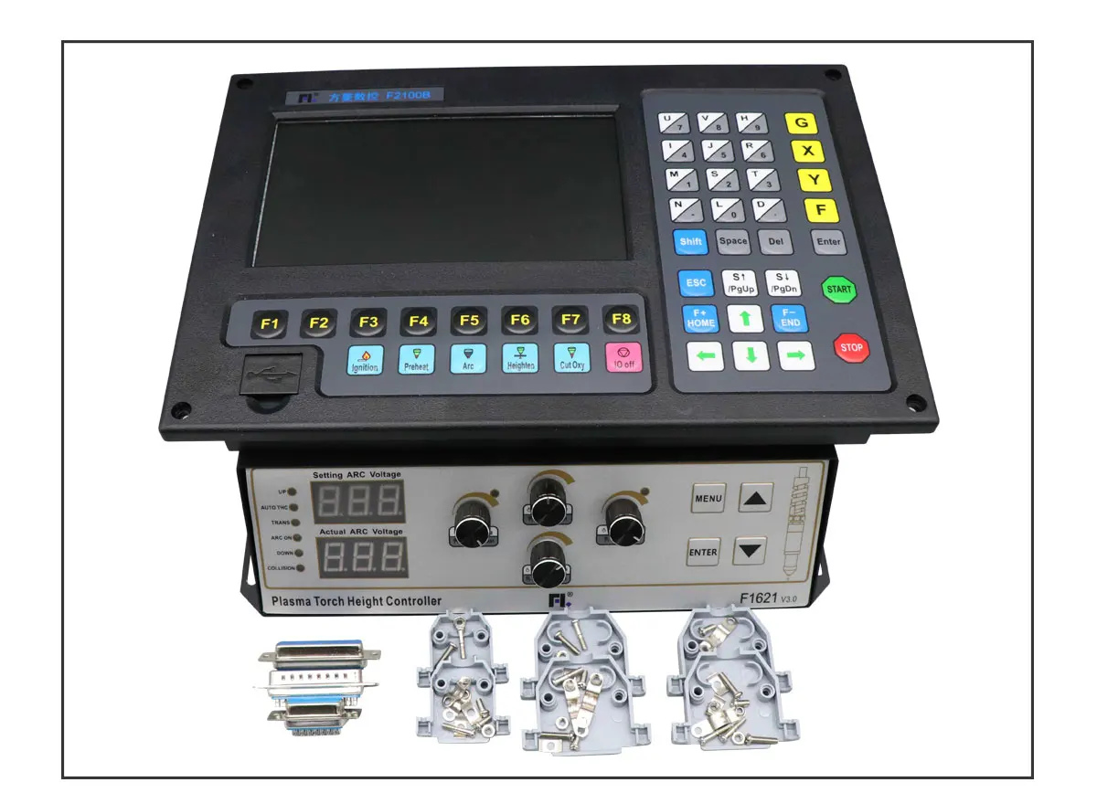
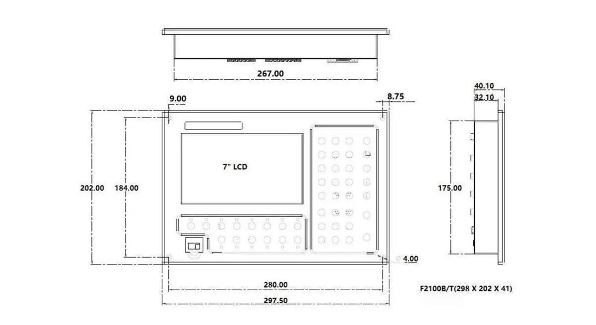
F2100, F2100T Hardware Configuration
1. Monitor:7 inch, 800*480, high definition 16 million colors and high
brightness LCD
2. Memory: 64M SDRAM
3. Program space available for user: 256M electronic hard disk
4. CPU frequency: 400MHz
5. USB: USB 1.1 front interface, at least 16GB U disk supportable
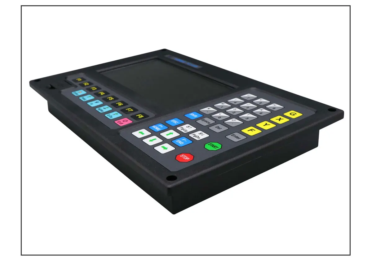
6. Keyboard: PCB keyboard
7. Chassis: full-steel structure completely shielded which defends electromagnetic
radiation, interference and static electricity
1.3 Technical Indicator
1) Control Axis: 2 axis linkage(3 axis customizable)
2) Control accuracy: +/-0.001mm
3) Coordinate range: +/- 99999.99mm
4) Max pulses: 200 kHz. Max speed: 15,000 mm/m
5) Max lines of code: 80,000lines
6) Max size of single code file: 4M
7) Time resolution: 10ms
8) Working Voltage: DC +24V direct-current power input, power > 80W.
9) Working Temperature: -10℃~+60℃. Relative Humidity, 0~95%.
10) Max power of drive arc THC motor: 45W (suitable for models with “T”). if need
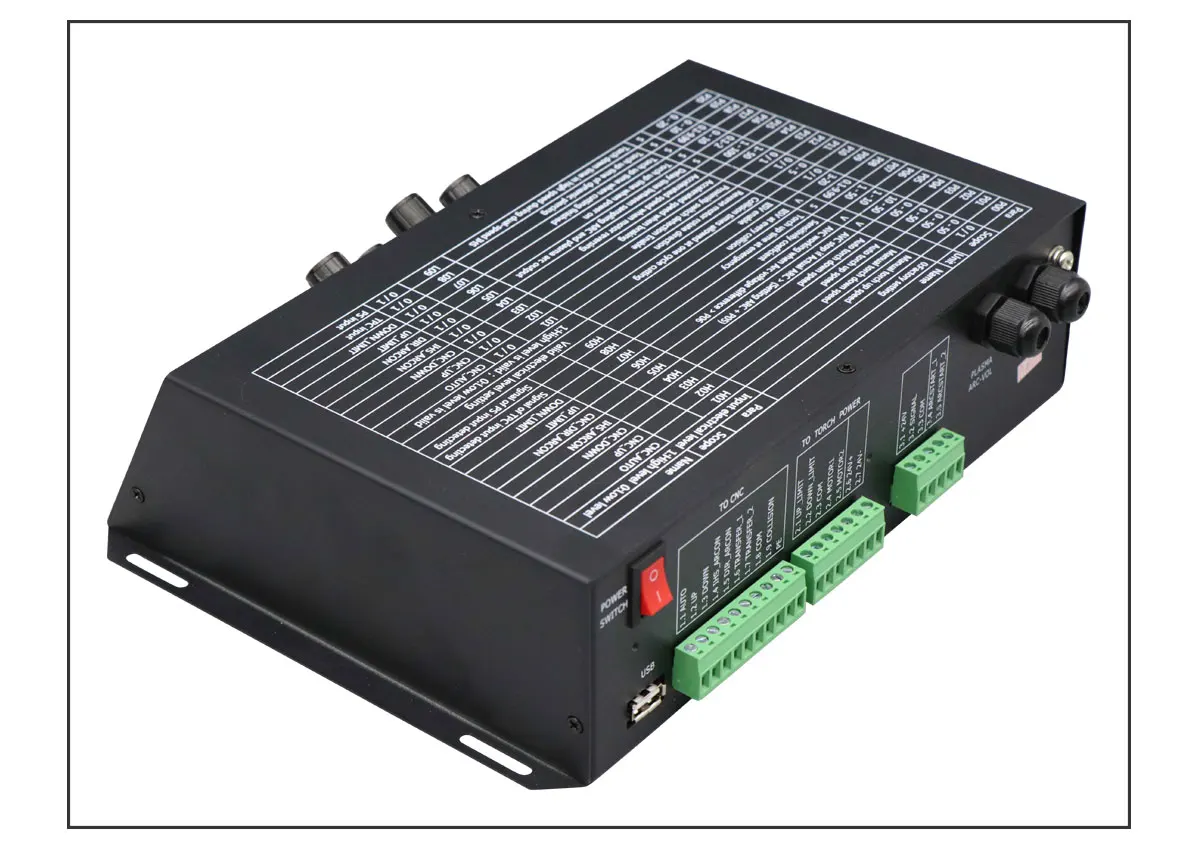
1.4 Controller Interface
a) DB15 pins SMA Male interface of 2 axes of motor drive.
b) DB25 pins SMA Female interface of 16 channels optoelectronic isolation output ports
max back flow current 300mA.
c) DB25 pins SMA Male interface of 16 channels optoelectronic isolation input ports,max
output current 300mA.
d) USB interface on the front panel, for the convenience of transmitting cutting code.
e) Extend IO input/output ports, PWM input ports, analog input ports.
f) Optional standard DB9 core male serial port RS232 interface.
g) 5 pins CAN bus connector.
The following three interfaces are only suitable for controller models with “T”:
h) Selection of partial pressure proportion of arc input: 1:50 or 1:100
i) 5 pins connector for THC motor output and limit input ports.
j) 7 pins connector for arc voltage and IHS port, arcing start output port.
F2100T controller links with location proximity switch, arc start of plasma power and arc voltage
divider by 7 pins socket, links with lifting motor by 5 pins socket.
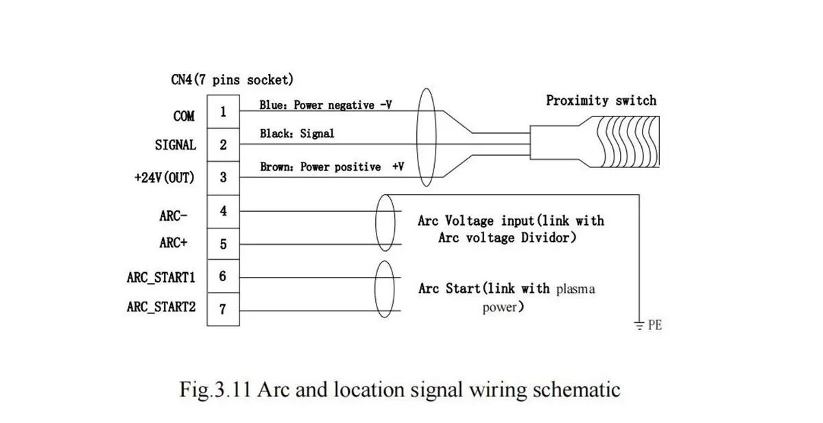
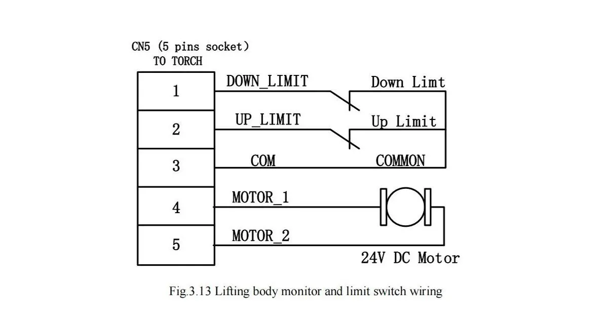
Note: please refer to the section of 11.4.5 to get detail of wiring interpretation with THC
module.
Technical parameters
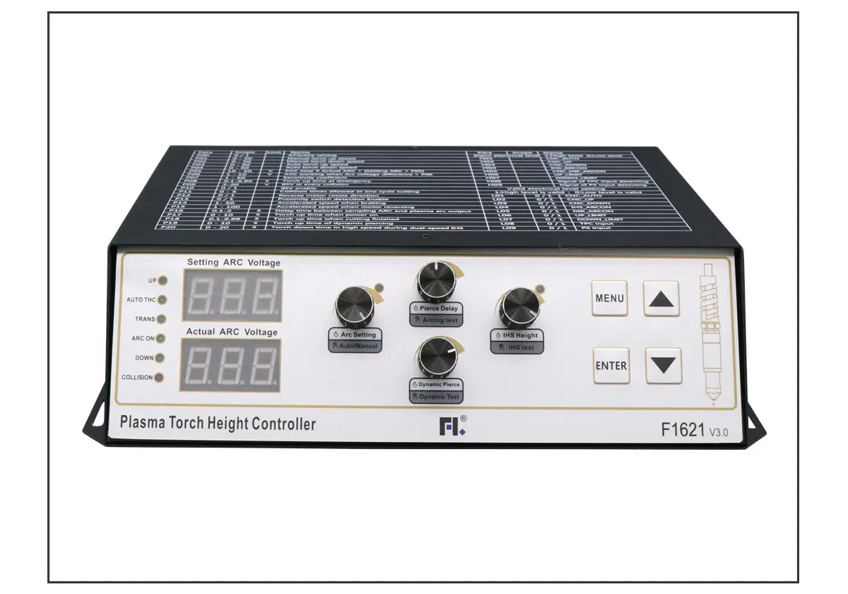
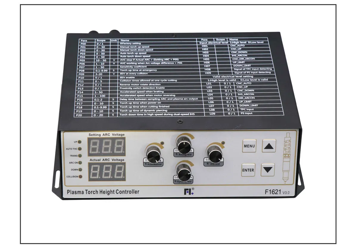
Table 3 F162X Series Height Controller Technical Parameters
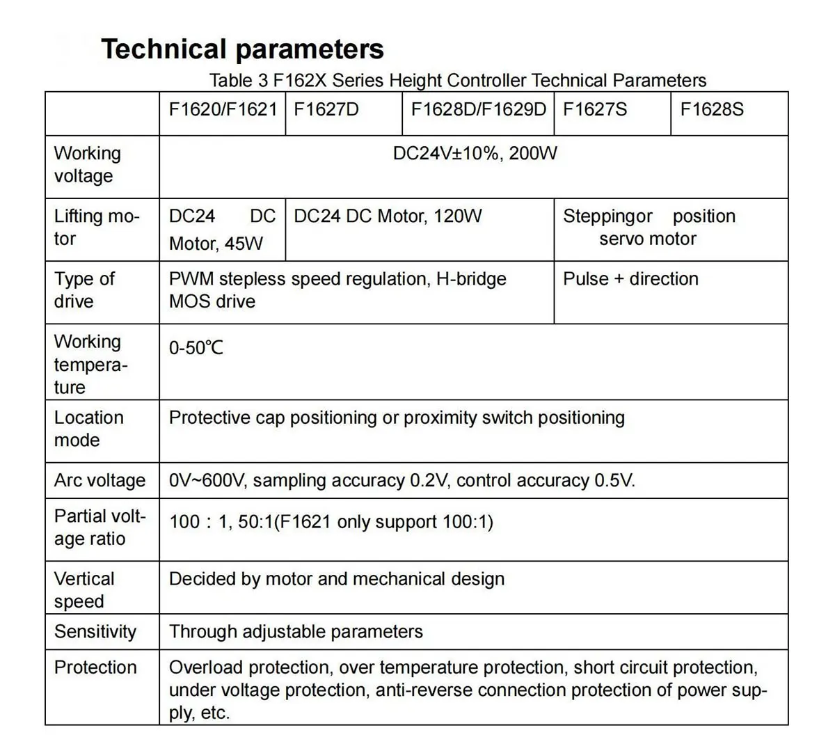
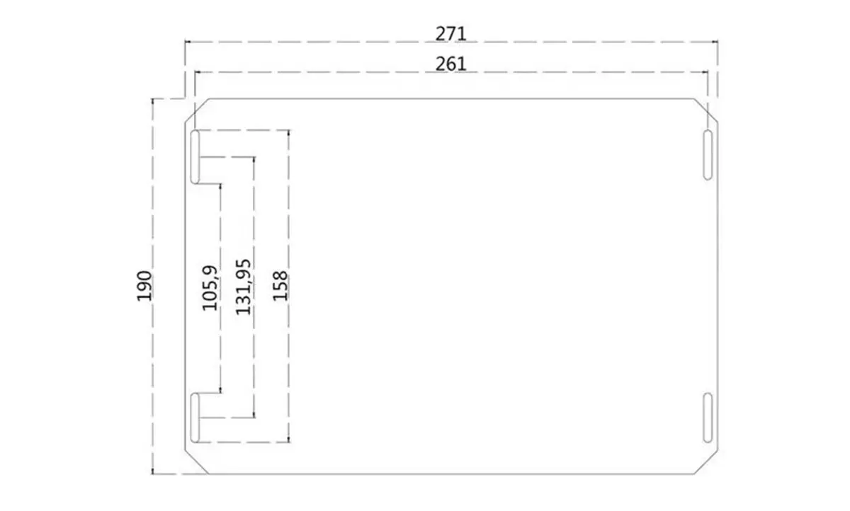
F1620/F1621 model
Chassis size: 271mm wide, 190mm deep (excluding rear terminal), 70mm high.
Chassis mounting screw positioning
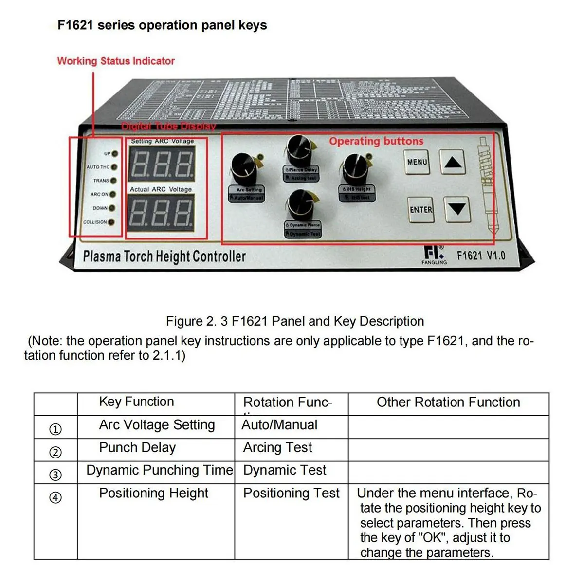
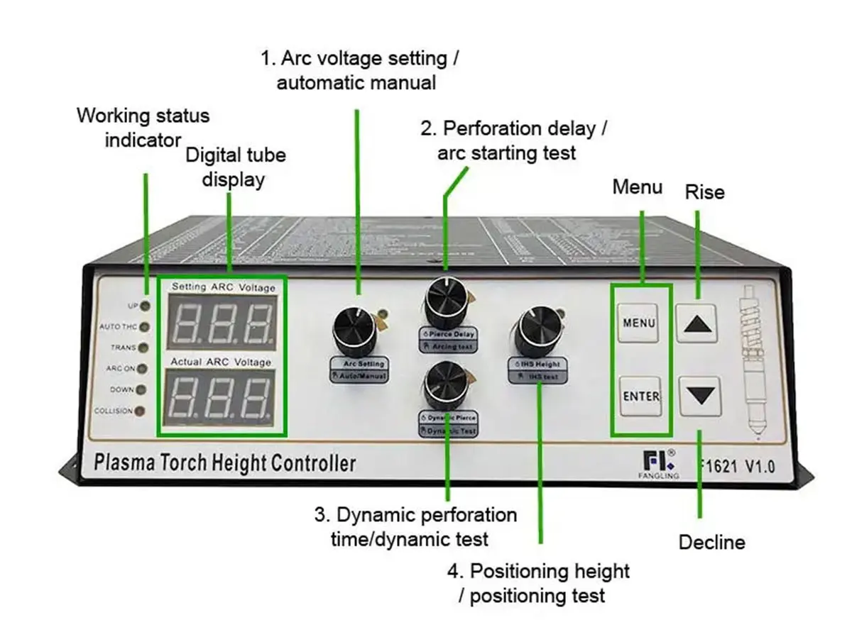
【▲】: Cutting torch up, Under the SYS interface, the gun is lowered to the ‘+’ button.
【▼】:Cutting torch down, Under the SYS interface, the gun is lowered into a ‘-’ button.
【Menu】: Enter the menu function key. In different states, it represents different
functions.
【Confirm】:The confirm button. After entering the menu, press this key for the first
time to enter the modification parameter. After the modification parameter is completed,
press this key again to confirm the modification parameter.
Equipment functions
1) Automatic initial positioning
Initial positioning is divided into proximity switch positioning detection mode and
protective cap collision detection mode
Ø Proximity switch positioning detection
NPN normally open proximity switch (or PNP normally open proximity switch) is
used in this equipment, and normally the proximity switch is in contact state. In the positioning test process or the initial positioning process during arcing, when the cutting
torch touches the work piece (or when the cutting torch tilts due to touching the work
piece), the proximity switch will disengage, the detection circuit detects the signal, and
the cutting torch will be up to the initial positioning height (the height value can be set
by the "positioning height" knob of the panel). When the proximity switch is disengaged, the cutting torch will up until it touches the up limit of the motor.
Ø Collision detection of protective cap
When the protective cap collision detection is adopted, the protective cap of the
cutting torch contacts the work piece in any state, and the detection circuit will act to
up the cutting torch to the initial positioning height (the height value can be set by the
"positioning height" knob of the panel). Under normal circumstances, after the cutting
torch ups, the protective cap leaves the work piece and the collision signal is reset
immediately. If the collision signal of the protective cap is maintained, the cutting
torch will up until it touches the up limit of the motor.
Ø Two speed positioning
After the initial positioning process starts, the cutting torch will descend for 6
seconds at the fastest speed (the time can be changed by parameters), and then
switch to low speed (low speed is 1/4 speed of high speed) until the cutting torch
collides with the workpiece. Through two-speed positioning, the working efficiency
can be improved, the speed can be reduced at a proper height, the collision impact
force can be reduced, and the service life of the protective cap can be prolonged.
2) Automatic arc voltage height control
If the actual arc voltage does not exceed the set value of 30V (this parameter can be
modified through the menu), the height controller will be in the Automatic height adjustment state.
3) Automatically up cutting torch after
collision
In case of collision under non-cutting and non-positioning conditions, the cutting torch
will be automatically up, and the time is the time for emergency collision and gun up. In
the process of initial positioning test or collision during cutting, the cutting torch will be automatically up for the initial positioning height time.
4) Automatically up the cutting torch after cutting is completed
After the cutting is completed, the cutting torch is automatically up, and the up height
can be set through parameters.
5) Manual operation
Automatic/manual height adjustment selection, manual up, manual downing, arcing
test, initial positioning test, menu operation and other functions can be realized through
the operation panel.
6) Automatic operation
After the numerical control system sends out the arcing signal, the height controller
automatically completes the actions of initial positioning, arcing and arcing success feedback. After the numerical control system receives the arcing success feedback signal, the
numerical control system controls the machine tool to start moving and cutting.
7) Arc voltage set point and actual value display monitoring function
The height controller uses two rows of high-brightness digital tubes to display the arc
voltage value, the up row of green digital tubes to display the arc voltage set value, and
the down row of red digital tubes to display the actual arc voltage value. It is convenient
for users to monitor the arc voltage value in the cutting process in real time.
8) Menu operation
In the non-cutting state, you can enter the menu mode to change the parameters by
pressing the panel key. Parameters such as speed and operation mode can be flexibly
set.
9) Knob operation
The panel has three operation knobs, which can set parameters such as arc voltage,
initial positioning height and perforation delay.
10) Effective level setting
The input switching value can be set to be low-level or high-level, which is flexible to
adapt to the complex application environment on site. The default is active low. Changes
can be made through the menu.
11) Anti-collision function
In the cutting process, if the cutting torch touches the workpiece due to too low arc
voltage setting or nozzle loss, the height controller will immediately send a up signal to
avoid damage caused by the cutting torch hitting the workpiece all the time. In case of collision in the cutting process, it is also possible to set the numerical control to stop cutting
after several collisions. By default, once collision occurs, the numerical control system will
be notified to stop cutting immediately. If the user does not connect the collision output
signal to the numerical control system, the numerical control system will continue cutting
when a collision occurs during cutting because the collision signal is not received. However, whether the numerical control system will stop cutting or not, in case of collision, the
height controller will automatically up the cutting torch to the initial positioning height.
In the non-cutting process, as long as the cutting torch touches the steel plate, the
cutting torch will automatically raise the height of a collision emergency up gun (normally,
the height is higher than the positioning height, and this parameter can be modified).
12) Intelligent adjustment for arc voltage
When using the arc voltage intelligent adjustment function, in the cutting process, if
the steel plate is touched twice in a row, the arc voltage setting value will Automatically increase by a preset value (the parameter can be modified and the default value is 5V). For
example, the current arc voltage setting value is 110V. After the steel plate is touched
twice in a row, the arc voltage setting value will automatically increase by 5V to 115V, thus
increasing the torch height and preventing the workpiece from colliding again in the continuous cutting process.
13) Dynamic perforation
In the cutting process, under the condition of perforation delay, the cutting torch can
be up to a height at the moment of Arcing, and the cutting torch can be downed to the
original height before the perforation delay is finished. This function is an approximate dynamic perforation function. When piercing, the cutting torch is up a little, which can effectively prevent slag splashing onto the cutting gun during piercing. If the dynamic perforation up time is set to 0, the cutting torch will not be up during arcing.
The dynamic perforation height can be adjusted in real time through the shortcut keys
of the operation panel.
14) Collision signal feedback
The height controller can immediately feed back the collision signal to the numerical
control system so as to prevent the cutting machine from still moving after collision. It is
also possible to set the height controller to feed back the collision signal to the numerical
control system after several collisions, so as to maintain the continuity of cutting (used
when cutting thin plates)