


The NISSCOM Cable is intended for Nissan and Infiniti cars build between years 2001 and 2008. Majority of these cars are equipped with a 16 pin OBDII connecter and use Consult II protocol over K line (DDL2). The connector is usually located near the fuse box.
The NISSCOM Cable supports factory OEM E-C-Us. Aftermarket E-C-Us are not compatible with this cable.
This Cable supports diagnostics of following control modules: CM, BCM, TCM, ABS, S-R-S and CMD (CM Diesel) over the K-line (DDL2).
Note: Some vehicles may use K-line for diagnostics of engine CU (CM) but still use DDL1 line for diagnostics of other control modules. This software does not support diagnostics over the DDL1 line.
ITCARDIAG NISSCOM Diagnostic Tool for Nissan and Infiniti Highlights:
1. Self Diagnostics:reads and resets CM, BCM, TCM, ABS, SR and CMD error codes.
2. Active Test:The Active Test function can be used to temporarily modify some of the engine parameters. They return to their original values when a function is stopped, PC disconnected, or engine restarted.
3. Work Support:
Clear Self Learn – clears the A/F Base SL map learned by the E-C-U.
Idle Air Volume Learn – is an operation to o learn the idle air volume that keeps each engine idle speed within the specific range.
Program Immobiliser Key – registers transponder keys with the Immobiliser Note: The immobiliser security PIN CODE needs to be known.
Steering Angle Sensor Reset – After removing/installing or replacing VDC/TCS/ABS control unit, steering angle sensor, steering components, suspension components, tyres, or after adjusting wheel alignment, make sure to adjust neutral position of steering angle sensor before running vehicle.
4. Cylinder Power Test,Speed Test
5. Log Analyser
6. Data Replay
7. Fuel System Status, Monitor Status
8. Wideband O2 sensor
language: English
Operating system: win7, win10
CM Functions :
CM Part Number

This is the main window of the NISSCOM software. It shows the CM Nissan Identification part number. Basic and Advance Functions can be selected by clicking on the buttons, using the shortcut keys (F1 – F11) or using the Menu bar. All real time functions are disabled until communication with the CU is established.
The progress bar at the bottom indicates communication between the CU and PC. If the bar is not moving, there is no data being received from the CU.
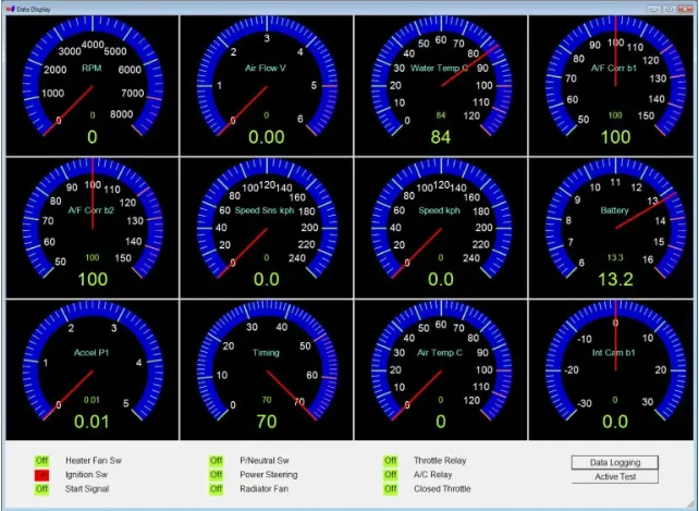
Data Display
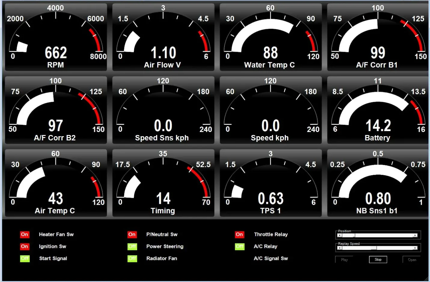
Classic design gauges
Modern design gauges
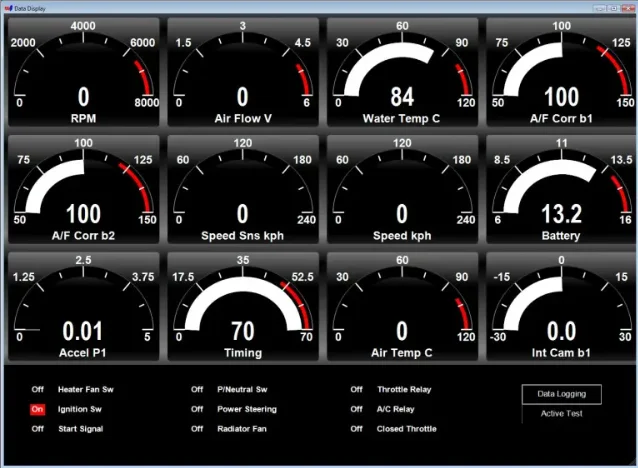
The Data Display function uses 12 gauges and 9 registers to display a real time information about the engine operation as measured or calculated by the engine CU. Parameters are assigned to gauges using the Data Display Settings function.
Data Display Settings
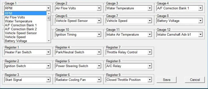
The Data Display Settings is used to assign parameters and registers to be displayed by the Data Display function. Only parameters that are supported by the currently connected CU are available for selection.
Work Support
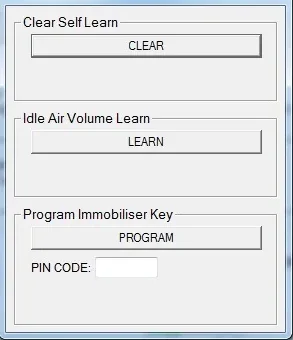
The Work Support functions allow users to perform some of the advance service procedures. Those procedures may need to be performed after replacement parts are installed.
Clear Self Learn – clears the A/F Base SL map learned by the CU.
Idle Air Volume Learn – is an operation to o learn the idle air volume that keeps each engine idle speed within the specific range.
Program Immobiliser Key – registers transponder keys with the Immobiliser Note: The immobiliser security PIN CODE needs to be known.
Cylinder Power Test
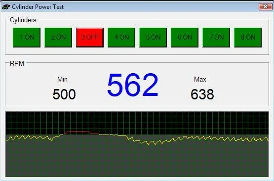
The Cylinder Power Test function can be used to identify cylinder that is underperforming. This function allows shutting down individual cylinders. If all of cylinders are producing the same amount of power, then the engine RPM will drop the same amount on each cylinder.
Live Graph
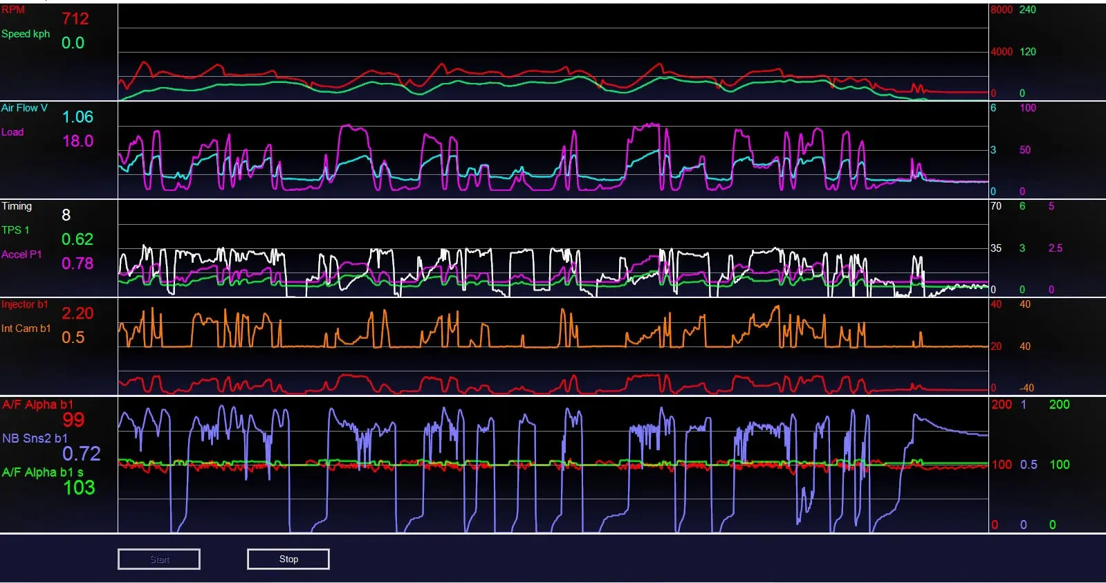
The Live Graph function has 5 sets of graphs to display live parameter and register readings. The reading can be stopped and restarted. This function is particularly useful for visualising parameter changes over time. The variables are assigned to graphs in the Live Graph Settings window
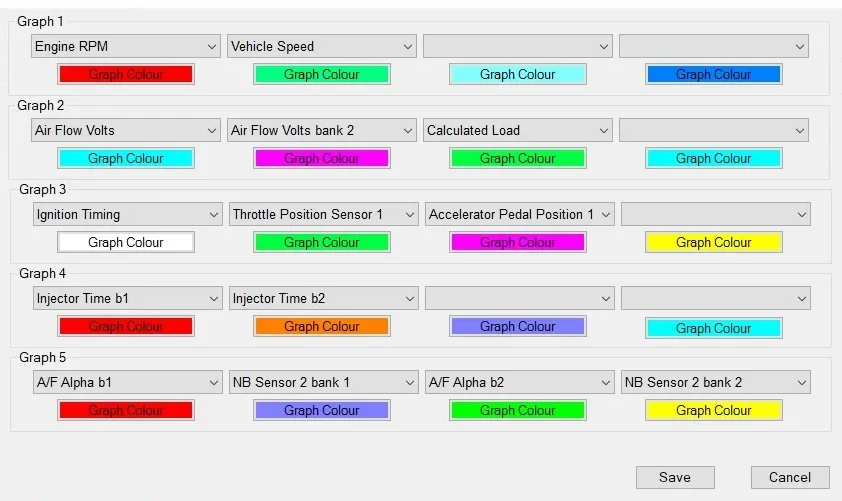
The Live Graph Settings function is used to assign parameters and registers to graphs in the Live Graph function. Only parameters and registers that are supported by the currently connected CU are available for selection. Graph colours can be individually customised.
Speed Test
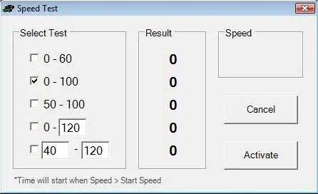
The Speed Test function is a unique function for measuring car’s acceleration performance. Predefined or user specified tests can be used. Due to the low resolution of Nissan speed sensors, measurements should only be used as a guide.
Note: This function should not be used while on public roads.
Address Watch
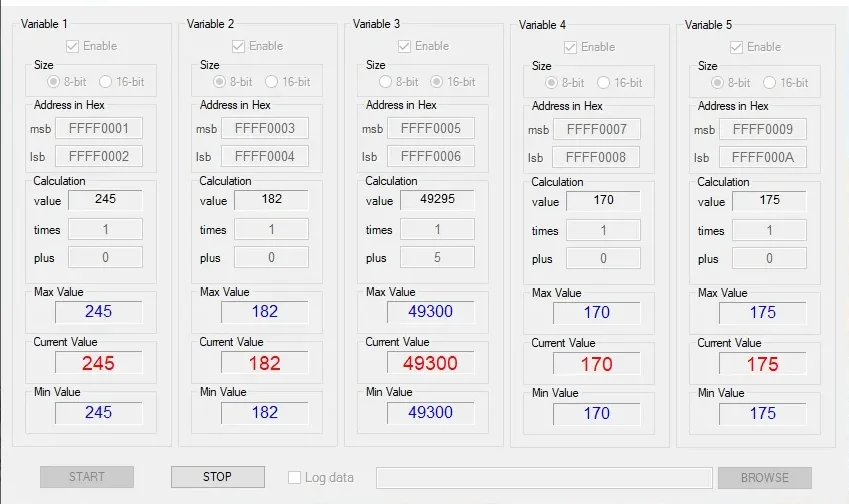
The Address Watch function is used for monitoring CU memory addresses. By monitoring a memory address additional information can be retrieved that is not normally available using the Consult II protocol. A knock sensor reading can be obtain using this method if knock sensor memory address is known.
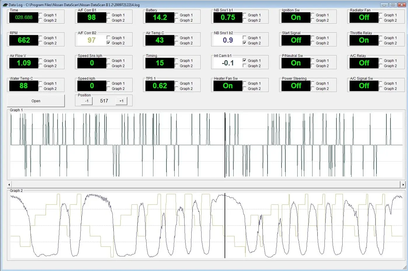
Log Analyser
Classic design
Modern design
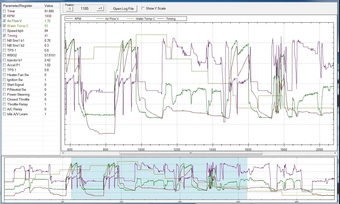
The Log Analyser function can be used to review log files previously generated with the Data Logging function. Graphs are drawn by selecting boxes next to parameter value. Graph colours match the parameter value colours.
Data Replay
Classic design gauges
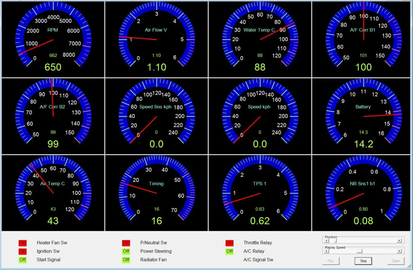
Modern design gauges
The Data Replay function replays previously saved data logs. Replay can be speeded up or slowed down using the Replay speed scroll bar. The Position scroll bar controls which log record is currently displayed.
BCM Functions:
BCM Part Number

The BCM tab shows the BCM Nissan Identification part number. Basic Functions can be selected by clicking on the buttons or using the Menu bar. All functions are disabled until communication with the CU is established.
The progress bar at the bottom indicates communication between the CU and PC. If the bar is not moving, there is no data being received from the CU.
Note: Nissan discontinued using k-line BCMs around year 2003. This means NISSCOM BCM diagnostics will not work on cars manufactured after year 2002.
Data Display
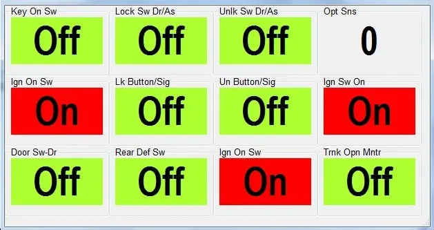
The Data Display function displays live data from the BCM. It can display up to 12 variables at the time. The parameters and registers to be displayed are assigned using the Data Display Settings function.
Self Diagnostics

The Self Diagnostics function reads and resets BCM error codes.
Active Test
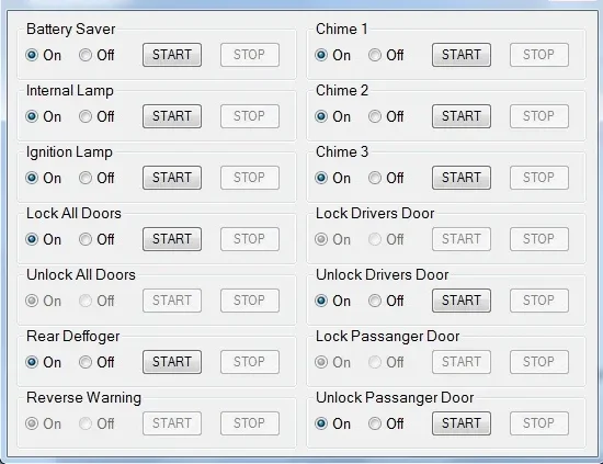
The Active Test function is used to temporally activate some of the BCM controls. It’s usually used to manually test functionality of the systems controlled by the BCM.
Note: Functions not supported by the BCM are disabled (greyed out).
ABS Functions:
ABS Part Number

The ABS tab shows the ABS Nissan Identification part number. Basic Functions can be selected by clicking on the buttons or using the Menu bar. All real time functions are disabled until communication with the CU is established.
The progress bar at the bottom indicates communication between the CU and PC. If the bar is not moving, there is no data being received from the CU.
T-C-M Functions:

The TCM tab shows the TCM Nissan Identification part number. Basic Functions can be selected by clicking on the buttons or using the Menu bar. All real time functions are disabled until communication with the CU is successfully established.
The progress bar at the bottom indicates communication between the CU and PC. If the bar is not moving, there is no data being received from the CU.
S-R-S Functions:

The SR tab shows the SR Nissan Identification part number. Basic Functions can be selected by clicking on the buttons or using the Menu bar. All functions are disabled until communication with the CU is established.
The progress bar at the bottom indicates communication between the CU and PC. If the bar is not moving, there is no data being received from the CU.
CMD Functions:

OBDII Functions:
Data Display
Classic design gauge

Modern design gauge

The Data Display function monitors one OBDII parameter at the time. The parameter to be monitored is selected from the drop-down list below the gauge.
Data Logging

Parameters can be logged to a file. The saved data log file can be analysed using the Log Analyser function.
Self Diagnostics

The Self Diagnostics function reads and resets CM error codes.
Fuel System Status

The Fuel System Status function shows if the car’s fuel system is running in Closed Loop mode.
Fuel systems do not normally refer to injector banks. They are intended to represent completely different fuel systems that can independently enter and exit closed loop fuel. Banks of injectors on a V-engine are generally not independent and share the same closed-loop enablement criteria.
Monitor Status

The Monitor Status function shows the current status of various monitoring systems used by the engine management system.
Log Analyser

The Log Analyser function is used to review log files previously generated by with Data Logging function. Graphs are drawn by selecting boxes next to parameter value. Graph colours match the parameter value colours.
Wideband O2 sensor

The NISSCOM software supports wideband Air/Fuel ratio meters from Innovate Motorsports. A second serial port is used to connect to the controller.
The data from the wideband meter can be displayed or logged in conjunction with other engine parameters using the Data Logging function.

