NEW Infinity Kappa 6, 7, 8 and 9 Crossover Filter Networks
You've never heard your Kappas sound this good!
This ad is for a matching pair (2) crossover boards
to replace your old Infinity Kappa speaker crossovers.
These boards are built new for each order
so please allow 2-3 weeks for delivery.
Choose the model you need at the top of this ad.
Kappa 6 - $ 345.00/pr.
Kappa 7 - $ 395.00/pr.
Kappa 8 - $ 445.00/pr.
Kappa 9 - $ 495.00/pr.
Shipping is FREE for US(48) Only.
|
A speaker's crossover is the "brain" circuit that directs audio frequency bands to the appropriate driver (low pitched sounds to the woofer, high pitched sounds to the tweeter). It also regulates impedance and phase attributes usually ignored by most speaker manufactures. Over the years we have developed a process for building crossovers that out perform the mass produced crossovers included in most store-bought speaker systems. We call it our EDC™ Procedure (Environmental Driver Control). Infinity is notorious for burning up their over-engineered and unserviceable crossovers. We've seen many Kappa's come into the shop with failed crossovers. The following is an example of another set of Kappa 9's with faulty crossovers. |
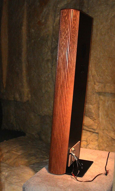
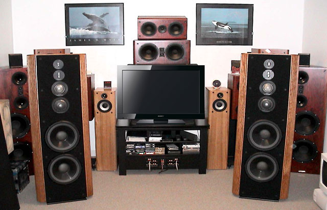 Infinity Kappa 9 Speaker Pair |
We do not attempt to repair the existing crossovers for several reasons:
|
|
|
We always choose to scrap the old crossovers and build new ones, however, one should not attempt this without facilities
such as an anechoic sound chamber with a high quality, full-range microphone, a computerized SPL response and impedance
sweep measurement system and complete loudspeaker/crossover simulation and optimizing software. We use the LinearX LMS
and LEAP systems for this. The EDC™ Procedure has
proven to be consistently accurate over many years. When the Kappa 9's first came in, we hooked them up to have a listen. Our amp went into "Protect" mode almost immediately. The Kappa's had nearly a dead short in the crossovers. This was not surprising, we've seen it before. So off to the anechoic sound chamber they went for impedance sweeps. Both Kappa's were identical in impedance with the result seen to the right ==> |
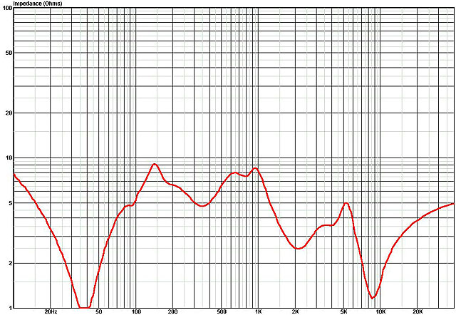 Original Impedance Sweep This graph shows severe instability below 70Hz and above 1.5KHz. |
|
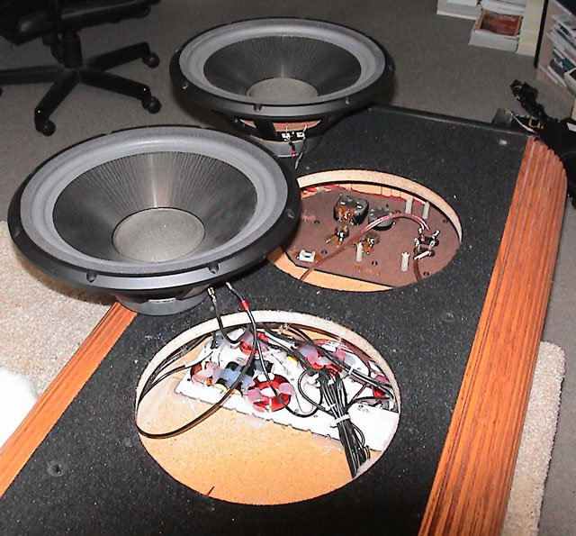
Out come the old crossovers ==> These boards were gutted saving only the binding post terminals and their leads. The L-pads (dials) were also left in place but not used. They almost always produce noise from scratchy pots. Even after contact spray the noise will come back. |
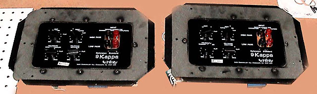  Original Crossovers |
| Next, the driver array was re-wired into a three-way system. All three tweeters were connected in series, the two mids and two woofers also connected in series. Individual leads from the three driver sections were fed through a temporary plate where the old crossover mounted. |
 Three SPL and impedance sweeps measuring each driver section |
|
We then began the EDC™ Procedure.
Separate SPL and impedance measurements were made of each driver section. ==> Notice the flat impedance of the tweeter section (blue) since ribbons have no enclosure resonance or voice-coil reactance. |
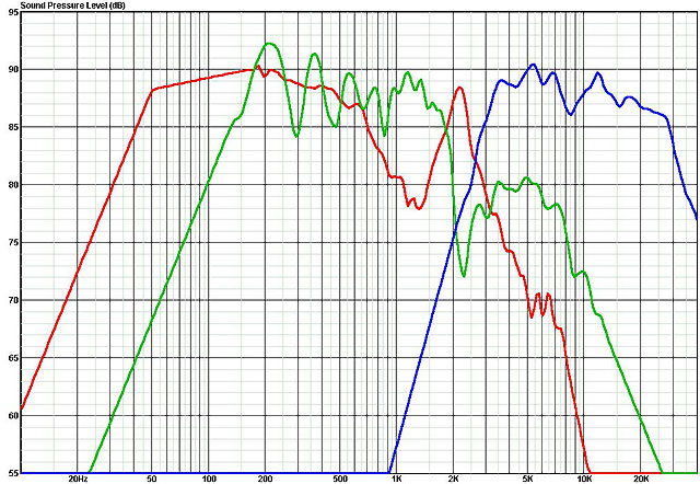 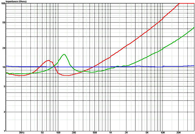 Measurements after rewiring for three-way design |
|
This measured data was imported into LEAP and the new crossovers were designed with many
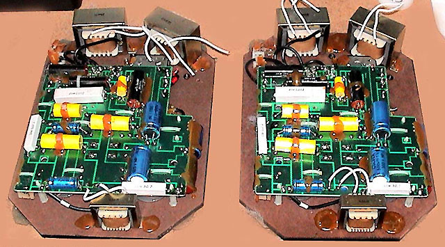
topologies investigated with the help of the software. The best design turned out to use a first-order filter (6db/Oct) for the woofers. The mids used a hybrid filter with a second-order filter (12db/Oct) on the low end and first-order filter for the upper end. The tweeters used a forth-order filter (24db/Oct). Crosspoints came out to be about 900Hz and 5KHz. I also added impedance flattening and phase stabilizing conjugate networks for the woofer and midrange sections. Biamping capabilities were maintained in the design. Parts were assembled and we began building. ==> |
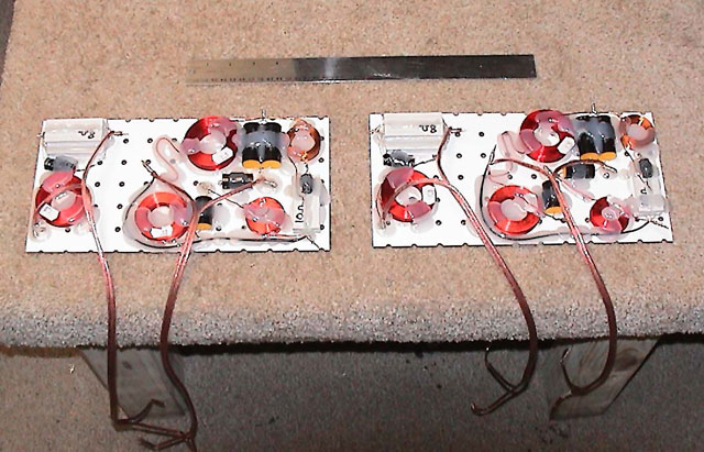
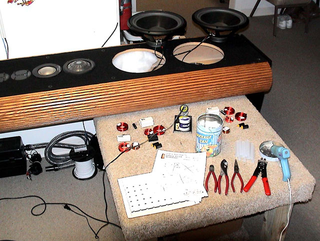 High quality components ready for assembly |
| The completed crossovers were then connected to each driver lead and transfer functions were confirmed using the LMS measurement system. ==> |
 Completed EDC Crossovers 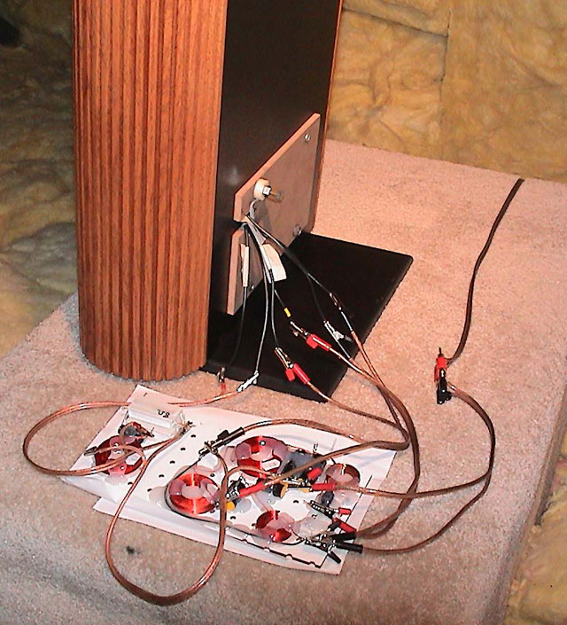 Testing each driver section |
|
LMS measured the transfer function of each driver section. ==> Notice how smooth the pass band areas are and the near "text book" rolloffs of each section. This is due to the conjugate networks added to drivers that have resonance and produce reactance. Ribbons have no voice coils to produce reactance so the tweeter section didn't need extra components. |
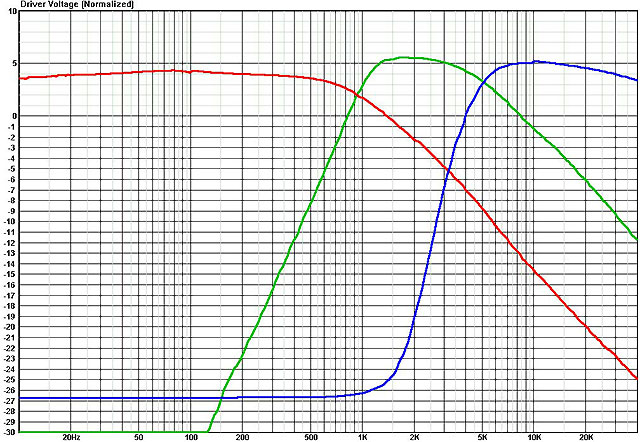 Filter Transfer Functions: Roll-off and Slope Verification |
|
The End Result: The frequency response is very flat at +/- 2db. The total impedance sweep is also solid at a nominal 6ohms. This makes the speaker very easy for amps to drive, even tube amps! SPL measurements were made at two(2) meters since the drivers were spaced apart a fair distance on the baffle. |
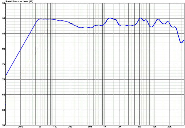 Final SPL Measurements 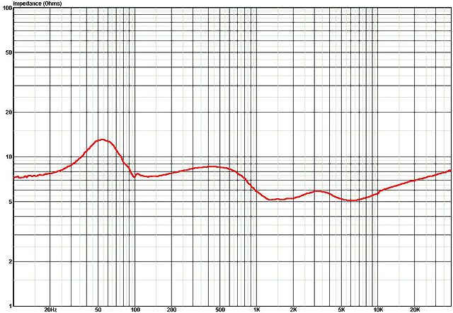 Final Impedance Measurements |
|
Installation: Full installation instructions are included with each set of crossovers. The original "gutted" crossover board was mounted back into the cabinet and the terminal leads from the new crossover were connected to the board's terminal post leads. Then the new crossovers where hot-glued to the back panel between the woofers. Driver section leads were connected to the new crossover and the woofers re-mounted. Done! |
 New Crossover Installation |
Customer's CommentsI am listening to an Audite recording of Mahler's 1st. It is a 386/32 bit digital recording that I made from the album. I am streaming it through my M2Tech Young DAC and I am hearing incredible detail and timbre. These speakers seem to get better every week or so. Totally unexpected sound. - Terry Franklin Hey Bill, My Kappas sound very good after changing the crossovers. Me and my friends are very impressed! Thank you! - Lars, Oslo Norway Bill, Thanks again! Did the refurb one at a time and the difference was unbelievable! In comparison, the old Infinity crossover design did appear to be an engineering over designed marvel. All done now and enjoying some good music ... but as my wife says probably a little too loud. Hope to do business again. Thanks! - Jerry, Palmdale CA Hello Bill, I bought from you the crossovers for Kappa 7 RS speakers couple months ago. I would like to thank you for a great job with them, they are awesome, brought my old speakers back to life and I enjoy them a lot. - Matej, Russia |
|