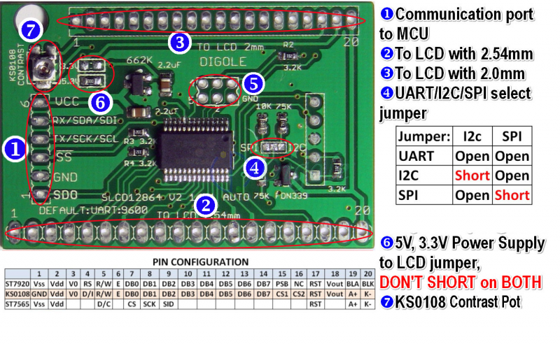
This Serial:UART/I2C/SPI Adapter can drive 128*64 dots LCD which on board controller is ST7920/KS0108/ST7565,
BACKLIGHT adjustable from 0%~100% Easy to use. Automatic detect ST7920, KS0108 and ST7565 (SPI) chip, no setting needed in most of case, also support ST7565 Parallel mode.
Firmware upgrade able
Works with 2.7V/3.3V/5.0V logic systems, 4bit/8bit/16bit/32bit micro-controllers. it EVEN works stand-alone.
Support serial (Hardware or Software): UART, I2C and SPI, set by the jumpers on PCB, support all four SPI mo.
7 fonts and graphic engine embedded, touch screen and flash chip drivers embedded(if touch screen or 2 to 16MB flash chip installed), custom fonts can be downloaded to the module's flash.
High level commands set (61 commands total) are easy to remember and understand, eg.: send 5 bytes: "CCabc" will draw a ratio=c pixels circle at coordinate (a,b) on the screen; 5 bytes "DNALL" will put the module to sleep mode(<0.1mA), and more...
/*
* compiled code size is about 5K
*/
#define _Digole_Serial_UART_ //To tell compiler compile the special communication only,
//other available is: _Digole_Serial_I2C_ and _Digole_Serial_SPI_
#include <DigoleSerial.h>
//--------UART setup, if you don't use UART, use // to comment following line
DigoleSerialDisp mydisp(&Serial, 9600); //UART:Pin 1(TX)on arduino to RX on module
//--------I2C setup, if you don't use I2C, use // to comment following 2 lines
//#include <Wire.h>
//DigoleSerialDisp mydisp(&Wire,'\x27'); //I2C:SDA (data line) is on analog input pin 4, and SCL (clock line) is on analog input pin 5
//--------SPI setup, if you don't use SPI, use // to comment following line
//DigoleSerialDisp mydisp(8,9,10); //SPI:Pin 8: data, 9:clock, 10: SS, you can assign 255 to SS, and hard ground SS pin on module
void setup() {
mydisp.begin();
mydisp.clearScreen();
mydisp.setMode('!'); //set graphic Drawing Mode to NOT
mydisp.setLinePattern(0xff);
mydisp.drawHLine(0, 31, 127); //draw horizontal LiNe
mydisp.setPrintPos(0, 31, 1); //Set Graphic position
for (uint8_t i = 1; i <= 127; i = i + 6) //this loop will draw sin graph
{
mydisp.drawLineTo(i, (uint8_t) (32 - (float) (sin(i * 3.14 / 63)*28)));
}
mydisp.setMode('C'); //set graphic Drawing Mode to COPY
mydisp.setLinePattern(0xaa); // set line pattern as dots
mydisp.drawLine(0, 0,127,0); //draw 4 horizontal dot lines
mydisp.drawLine(0, 15,127,15);
mydisp.drawLine(0, 47,127,47);
mydisp.drawLine(0, 63,127,63);
mydisp.setFont(10);
mydisp.drawStr(10, 0, "SIN Singal");
mydisp.setFont(6);
delay(300); //for ST7920, due to this kind of display is slower thant others
for (uint8_t i = 0; i <= 127; i +=16 ) //this loop will draw vertical lines and Coordinate values
{
mydisp.setLinePattern(0x72);
mydisp.drawVLine(i,0,63); //draw one vertival line use pattern 0x72 (dash)
mydisp.setRotation(1); //rotate to 90 degree
mydisp.setTextPosAbs(32, 127-i+3); //set text position as pixel
mydisp.print(i); //draw Coordinate value
mydisp.undoRotation(); //set rotation back to 0
delay(100); // for ST7920 or other slow LCD
}
}
void loop() {
}
Because the ST7565 chip used widely in 12864 LCD panels, and it’s very flexible of configuration, you need set at least 8 bytes of init parameters, if the ST7565 (SPI) not working well with this adapter, please use command “SLCD2” following by 8 bytes of init parameters also:


 1269
1269