NOTE:
1.Before purchasing the product, please check whether your motorcycle connector is compatible with my product connector.
2.There is a product installation video below. If necessary, you can directly watch the video reference for the link. If you have any questions, please contact me in time, I will be happy to answer it for you.
Fitment
For Suzuki GSF600 Bandit 2000-2004
For Suzuki GSF650 Bandit 2005-2006
For Suzuki GSF1200 Bandit 2001-2006
For Suzuki XF650 Freezing 1997-2004
For Suzuki VL800 intruder Volusia 2001-2004
For Suzuki SV650 1999-2002
For Suzuki GSX1300R Hayabusa 1999-2007
For Suzuki GSX750F Katana 1998-2006
For Suzuki GSX600F Katana 1998-2006
For Suzuki GSX-R750 1996-2019
For Suzuki GSX-R600 1997-2019 K1 K2 K3
For Suzuki GSR600 ALL YEARS
For Suzuki GSR750 2011-2017
For Suzuki DL650 Vstrom 2012-2019
For Suzuki DL650XT Vstrom 1999-2002
For Suzuki TL1000 R/S 1998-2003
For Suzuki VL1500 intruder 2013-2017
For Suzuki VZR1800 2011-2019
For Suzuki intruder c1500 2013-2017
For Suzuki Boulevard c90 2013-2019
For Suzuki GSX250R 2018-2019
For Suzuki GSX1000F Katana 2019
For Suzuki GSX1400 2001-2009
For Suzuki GSXR1000 2001-2016
For Suzuki GSXS750 2015-2019
For Suzuki GSXS750Z 2018-2019
For Suzuki GSXS1000 /F/A/FA 2015-2019
For Suzuki GSXS1000Z 2018-2019
Features:
Condition:100% Brand New
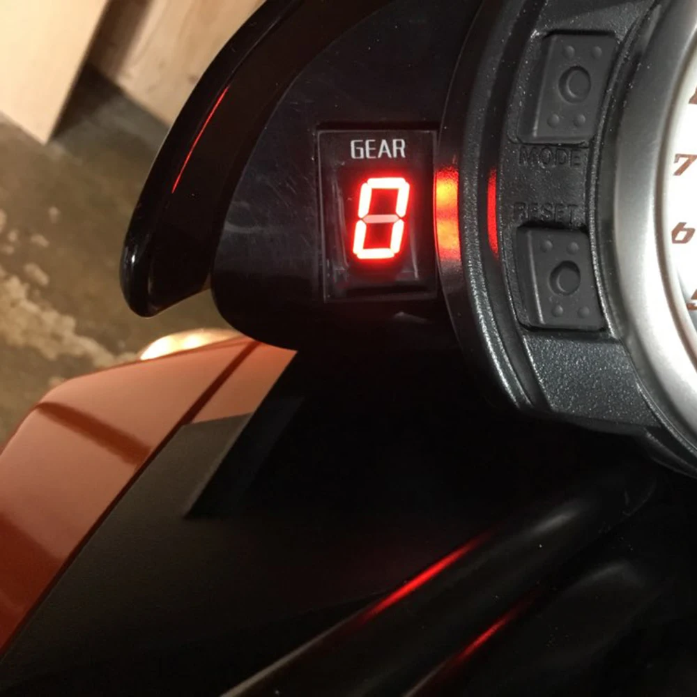
Gear indicatior Light Color: Red
Color of gear indicator bracket: black red green blue
1-6 Level Waterproof Gear display
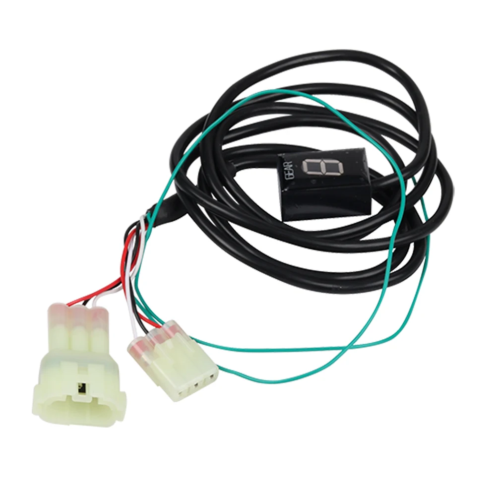
Locate the Speed Sensor connector:
The Speed Sensor is usually mounted on the front sprocket cover, and the 3-pole black speed sensor coupler (as shown in the figure) is situated 20-40 cm (8”-16”) away from sensor.
The connector is accessible by raising the fuel tank, removing the seat or a side fairing(as shown in the figure).
Confirmation:
1. Separate the Speed Sensor connector (you might need to use a small flathead screwdriver to get the connector apart).
2. After separating the Speed Sensor connector, plug in both the male and female 3-pole GFYSHIP harness connectors. Make sure the connectors are fully seated.
3. Find the wire that comes from the Signal generator (Pickup coil / CKP sensor).
If in doubt, check the bike’s Service Manual or ask your dealer.
4. Connect the Green wire to this wire, using the Red wire tap connector supplied.(The green wire is connected to the crankshaft sensor signal line)
Setup:
You need to setup the module after installation. When ignition is turned on, the display counts backwards (6 to 1) indicating that the memory is clear.
- Raise the rear wheel off the ground by using a stand, and start the engine in Neutral. (If you do not have a center stand, you can find a long and straight road with light traffic.)
-When the gear indicator screen displays "L", it means to start learning; Slowly accelerate through the throttle handle,
-When the gear indicator displays "1", please select the first gear,The display is blinking faster while the unit is learning the gear,release the clutch, and keep the RPM above idle speed;
-When the gear indicator displays "2", please select the second gear;
-Repeat this process until all gears are thought (5 or 6).
-The unit is programmed and should indicate the gears correctly.
-Now, when ignition is turned on, the display counts forward (1 to 6) indicating
that it is fully functional.
The steps to reset the product:
Turn on the key switch of the switch lock. When the gear indicator shows 3, turn off the key switch of the switch lock immediately, and then turn on the key switch of the switch lock immediately. According to the above operation, turn on and turn off the key switch of the switch lock six times in a row to see if the reset is complete(When ignition is turned on, the display counts backwards (6 to 1) Indicates that the memory has been cleared). Thank you