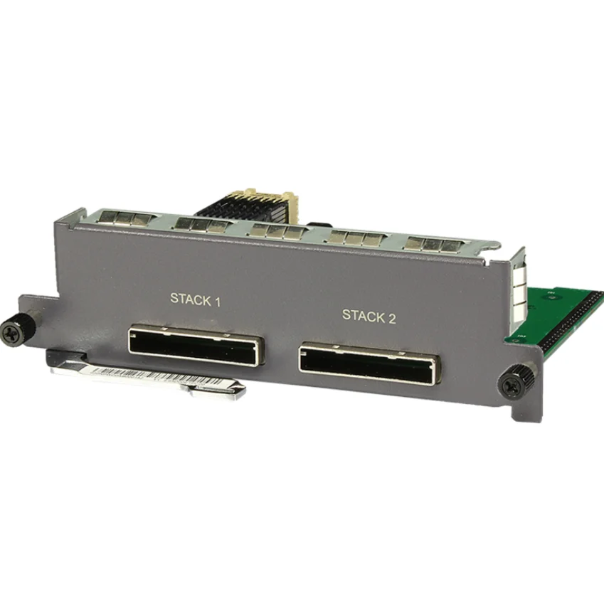
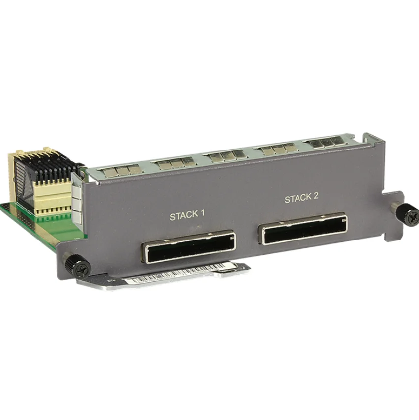
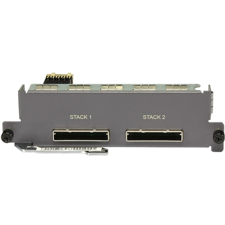
ES5D00ETPC00 S5700 series switches after stacking card
Software companionship
| The card model |
Imprint |
|---|---|
| ES5D00ETPC00
Illustrate:
After using the display device command, the PCB model of the plug-in card is displayed, corresponding to the CX22ETPC. |
V100R005C01 TO V200R005C03 VERSIONS ARE SUPPORTED.
Illustrate:
V200R003C02, V200R003C10 VERSIONS ARE NOT SUPPORTED. |
Plug-in card overview
Stacking iStack (Intelligent Stack) refers to the combination of multiple switch devices that support stacking characteristics, and logically combine them into a single overall switching device.
BEFORE THE ESTABLISHMENT OF THE STACKING SYSTEM, EACH SWITCH IS A SEPARATE ENTITY, WITH ITS OWN INDEPENDENT IP ADDRESS AND MAC ADDRESS, EXTERNALLY REFLECTED AS MULTIPLE SWITCHES, USERS NEED TO MANAGE ALL THE SWITCHES INDEPENDENTLY; AFTER THE STACK IS ESTABLISHED, THE STACK MEMBERS ARE EXTERNALLY REFLECTED AS A UNIFIED LOGICAL ENTITY, AND THE USER USES AN IP ADDRESS TO MANAGE AND MAINTAIN ALL THE SWITCHES IN THE STACK. THROUGH SWITCH STACKING, NETWORK LARGE DATA VOLUME FORWARDING AND NETWORK RELIABILITY CAN BE REALIZED, WHILE SIMPLIFYING NETWORK MANAGEMENT.
STACKING CAN BE DIVIDED INTO SERVICE PORT STACKING AND STACKING CARD STACKING, AND ES5D00ETPC00 IS USED FOR STACKING CARD STACKING.
| Plug in the card |
Device model |
|---|---|
| ES5D00ETPC00 |
|
ES5D00ETPC00 functions and features
| Functions and features |
Description |
|---|---|
| Basic functionality |
The ES5D00ETPC00 provides two 12Gbit/s rate electrical interfaces for device-to-device stacking card stacking, using dedicated PCIe stacking cables for connection. |
| Connection topology |
Compared with the chain topology, the ring topology has higher reliability, because when the link failure occurs in the chain topology, it will cause stack splitting; and when a link in the ring topology fails, a chain topology will be formed, and the stacked business will not be affected. the chain topology and the ring topology are connected as shown in fig. 8-91 and fig. 8-92.
Illustrate:
stack1 ports on one switch can only be connected to the stack2 port of another switch when stacking. |
Interface description
| Attribute |
Description |
|---|---|
| Connector type |
PCIe |
| Complies with standards |
IEEE 802.3ae |
| Support frame formats |
Ethernet_II,Ethernet_SAP,Ethernet_SNAP |
| Supports network protocols |
IP |
Specifications for ES5D00ETPC00
| Parameter items |
Description |
|---|---|
| Physical parameters |
|