PACKAGE CONTENT: ( NOT include Compute Module 4 )
All-in-one kit x1
12V 2A power Adapter x1
Screwdriver x1
Wiki English manual: waveshare.com/wiki/CM4-DISP-BASE-7A-BOX
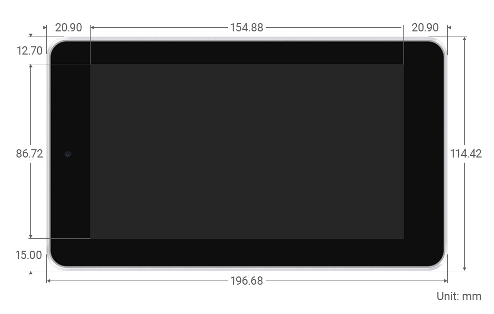
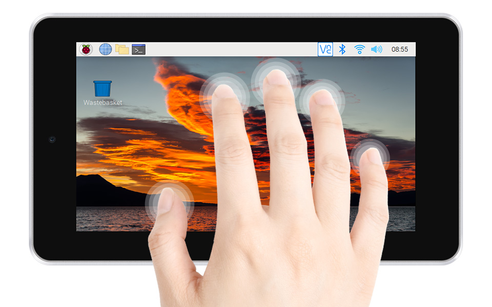
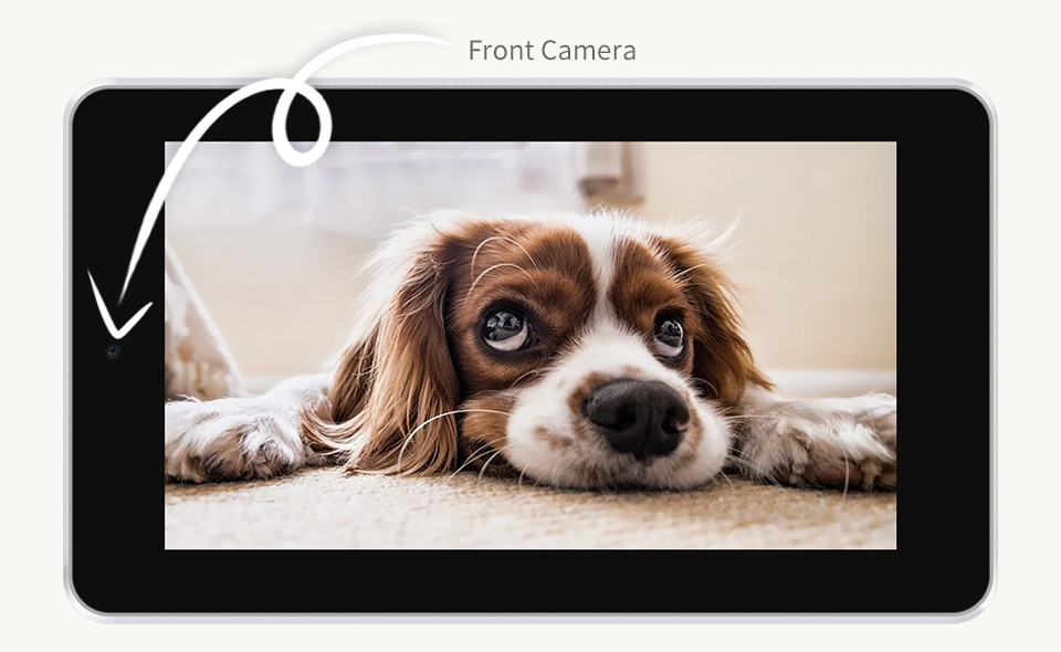
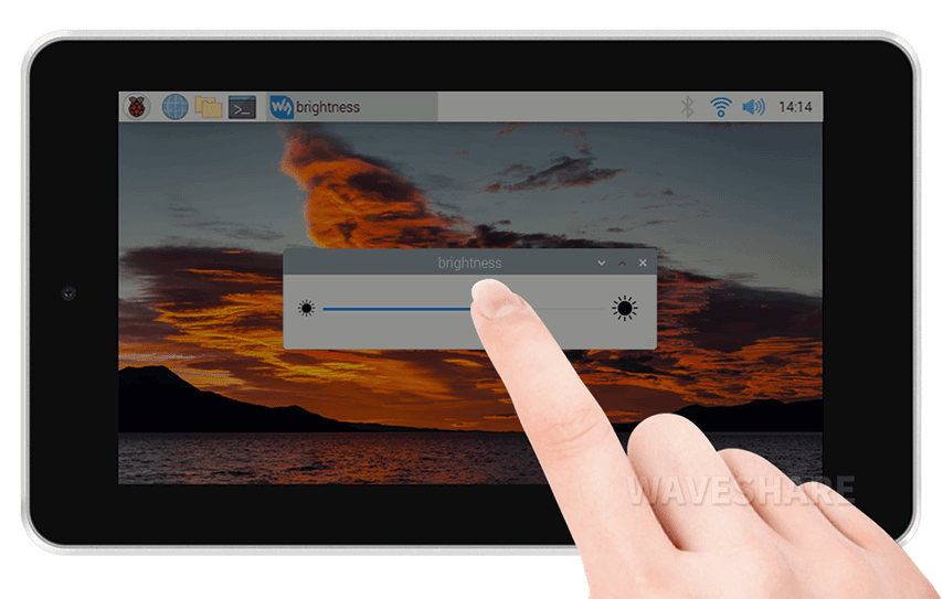
7inch Capacitive Touch Screen, 5-Points Capacitive Touch Along With Toughened Glass Panel, More Safe To Use
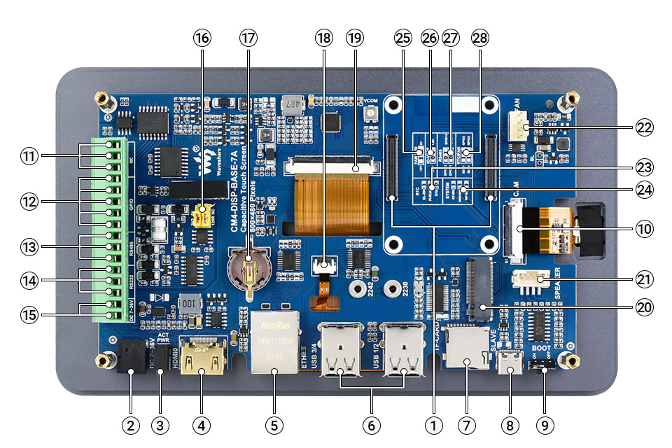
CM4 socket suitable for all variants of Compute Module 4
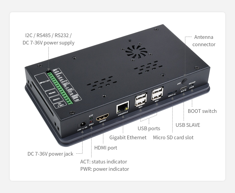
DC power supply 7 ~ 36V DC input
CM4 status indicator PWR: Raspberry Pi power indicator ACT: Raspberry Pi operating status indicator
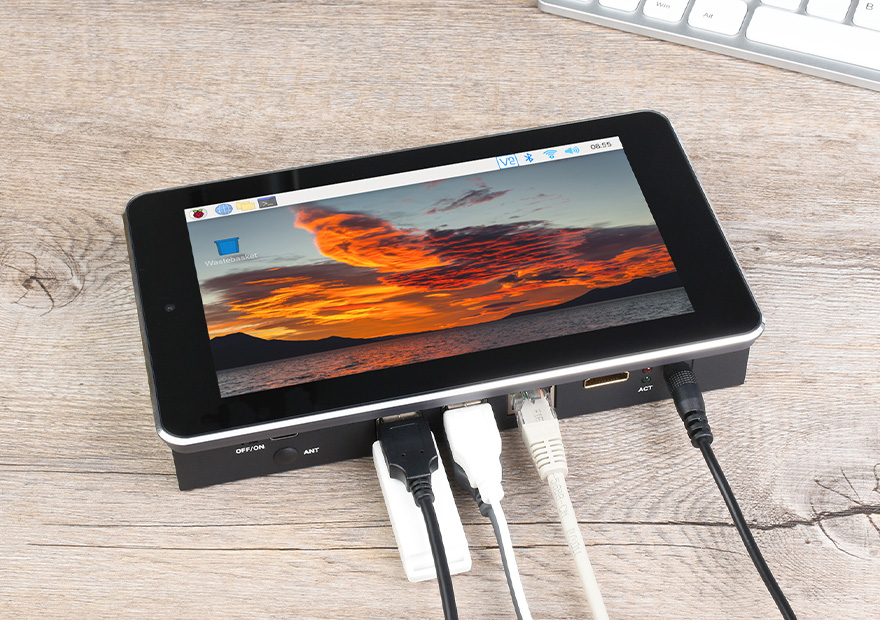
HDMI connector supports 4K 30fps output
RJ45 Gigabit Ethernet 10/100/1000M compatible
USB 2.0 ports 4x USB 2.0, for connecting sorts of USB devices
Micro SD card slot for connecting a Micro SD card with pre-burnt image (Lite variant ONLY)
USB SLAVE port USB programming port
BOOT selection ON: CM4 will be booted from USB-C interface OFF: CM4 will be booted from eMMC or Micro SD card
MIPI CSI connector connected to the 5MP front camera
Isolated I2C for controlling or reading data from devices via I2C
Isolated GPIO for controlling or detecting devices via GPIO
Isolated RS485
Isolated RS232
DC power supply 7 ~ 36V DC input
RS485 terminal resistor and GPIO logic level selection RS485: connect/disconnect the 120R resistor GPIO: GPIO logic level selection
RTC battery holder supports CR1220 button cell
Touch screen header connected to the capacitive touch screen
Display connector connected to the 7inch 800×480 display
M.2 M KEY supports M.2 M KEY NVME SSD, or other communication modules using PCIe channel
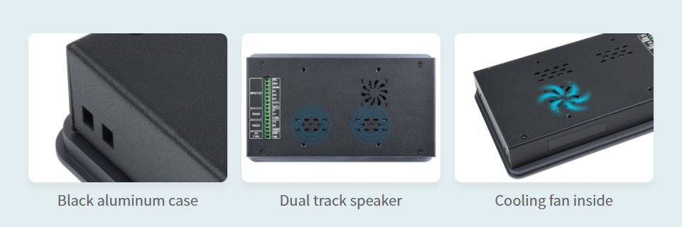
Speaker header audio output
FAN header for connecting cooling fan, allows speed adjustment and measurement
RTC interruption configuration GL-EN: CM4 powerdown on RTC interruption PI-RUN: CM4 will reboot on RTC interruption D16: D16 pin is triggered on RTC interruption (default)
System function configuration BT_DIS: Bluetooth disabled, for CM4 with antenna variant ONLY WiFi_DIS: WiFi disabled, for CM4 with antenna variant ONLY WP_DIS: boot mode switch, ONLY be used when NOT booted from eMMC or SD card
FAN power supply selection select 5V (default) or 12V power to drive the fan
IO-VREF selection set the CM4 IO logic level as 3.3V (default) or 1.8V
RS485 switch GPIO13/12: using ttyAMA1 device (default) GPIO15/14: using ttyS0 device
RTC/FAN I2C bus selection SDA0/SCL0: I2C-10 is shared with CSI/DSI GPIO3/2: I2C-1 is shared with 40PIN GPIO (default)