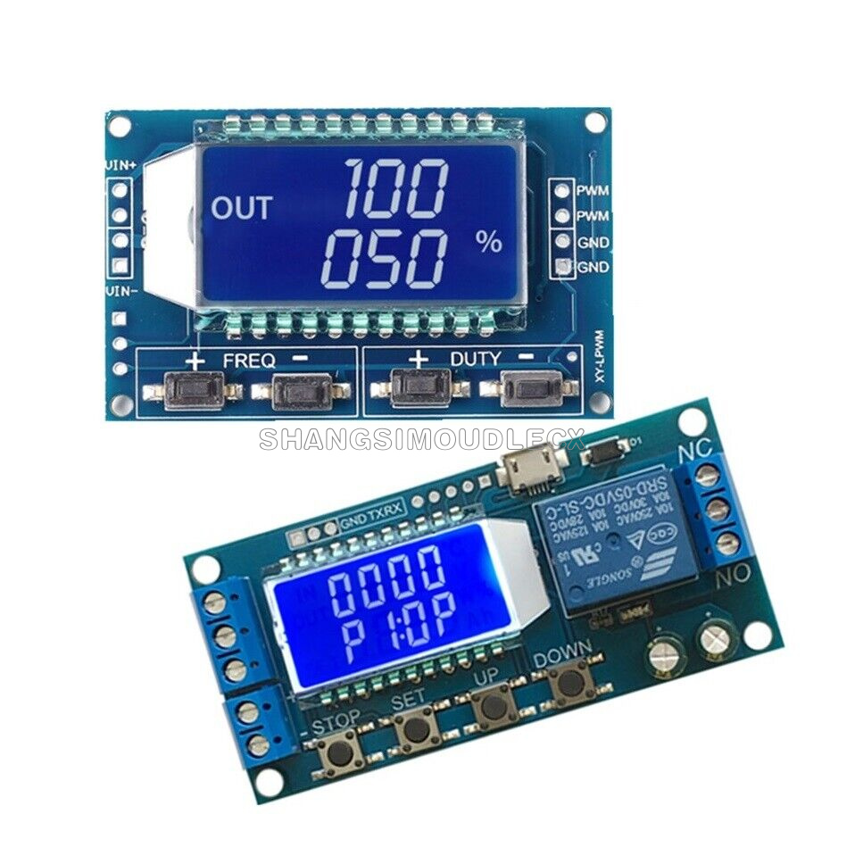
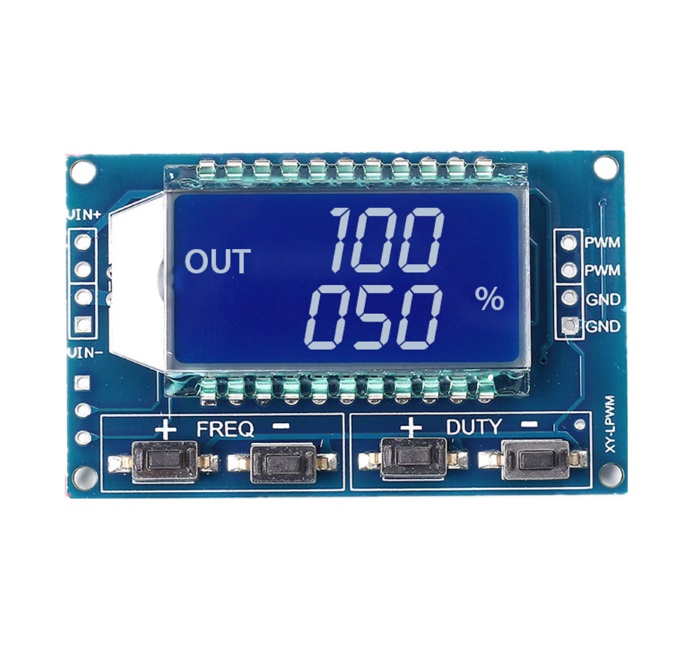
1. Signal PWM LCD Generator
Module Highlights:
1.LCD display frequency and duty cycle, very clear, PWM output can be set to the frequency and duty cycle;
- Wide frequency range, high precision;
- Serial communication, TTL level
First, the module description
PWM output, you can set the frequency, duty cycle;
Frequency is divided into four ranges, automatic switching:
- XXX (no decimal point): the smallest unit is 1Hz, the value range of 1Hz ~ 999Hz;
- X.XX (decimal point in the hundred) the smallest unit is 0.01Khz, the range of 1.00Khz ~ 9.99Khz;
- XX.X (decimal point in ten): the smallest unit is 0.1Khz; value range of 10.0KHz ~ 99.9KHz
- X.X.X (decimal point in ten and hundred): the smallest unit is 1Khz; value range 1KHz ~ 150KHz
frequency display: 100 indicates PWM output 100Hz pulse;
1.01 indicates PWM output 1.01K pulse;
54.1 indicates that the PWM output has a pulse of 54.1 kHz;
1.2.4 indicates that the PWM output is 124 kHz pulse;
Duty cycle range: 0 ~ 100%;
All set parameters, power-down automatically saved.
Second, the parameter settings
The module has four independent keys, used to set the frequency and duty cycle, support touch (increase or decrease a unit) and long press (fast increase or decrease), set the parameters automatically save, power down Not lost.
Third, the module parameters:
- Working voltage: 3.3 ~ 30V;
- Frequency range: 1Hz ~ 150KHz;
- Frequency accuracy: the accuracy in each range is about 2%;
- Signal load capacity: the output current can be about 5 ~ 30ma;
- Output amplitude: PWM amplitude equal to the supply voltage;
- Ambient temperature: -20 ~ +70 ℃.
Fourth, the scope of application:
- Used as a square wave signal generator, generate square wave signal for experimental development and use;
- Used to generate a square wave signal that controls the motor driver;
- generate adjustable pulse for MCU use;
- generate adjustable pulse, control the relevant circuit (PWM dimming speed and other applications).
5, serial control (single-chip TTL level communication)
Communication standard:
9600 bps Data bits: 8
Stop bit: 1
Check digit: none
Flow control: none
1, set the frequency of the PWM
"F101": Set the frequency to 101 HZ (001 to 999)
"F1.05": set the frequency of 1.05 KHZ (1.00 ~ 9.99)
"F10.5": Set the frequency to 10.5KHZ (10.0 ~ 99.9)
"F1.0.5": set the frequency of 105KHZ (1.0.0 ~ 1.5.0)
2, set the PWM duty cycle
"DXXX": set the PWM duty cycle to XXX; (001 ~ 100)
Such as D050, set the PWM duty cycle is 50%
3, read the set parameters
Send a "read" string to read the set parameters.
Set successfully return: DOWN;
Setup failed to return: FALL.
Package Included: 1 x PWM Pulse Frequency Duty Cycle Adjustable Module Square Wave Signal Generator
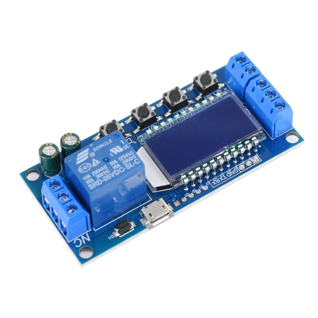
2. 5V Trigger Time Delay LCD
Timing Range:0.01 sec~9999 min
This product lcd display, very clear, simple and easy to use, powerful, but please read user instructions carefully before using.
Product Highlights:
1. Display with LCD two columns, Can display parameters directly;
2. Trigger mode: high and low level,switch quantity.meet most of the needs.
3. Power supply: 6~30V, also supports micro USB 5.0V, very convenient.Anti back connection of power supply.
4. Parameters can be modified via UART.
5. Stop button to provide emergency stop function.
6. 5 minutes without any operation into a low-power state. Any action wake up.
7. OP/CL/LOP params can be modified individually
8. All parameters are automatically saved by power off.
Working Mode Introduction(P1~P7)
P1: After the signal is triggered, the relay conduction in OP time then disconnects; In the OP time, the signal is invalid.
P2: After the signal is triggered, the relay conduction in OP time then disconnects; In the OP time, the signal triggers a new timer.
P3: After the signal is triggered, the relay conduction in OP time then disconnects; In the OP time, signal trigger reset timer,relay disconnected and stop timing.
P4: When triggered, After the relay is disconnected from CL time, relay conduction OP time, after timing is complete, disconnect relay.
P5: When triggered, After the relay conduction op time, the relay disconnects the CL time, and then loops the above action, gives the signal again in the loop, relays disconnect, stops the timer, and the number of cycles (LOP) can be set;
P6: When triggered, After the relay conduction op time, the relay disconnects the CL time, and then loops the above action, signal is invalid in the loop, the number of cycles (LOP) can be set;
P7: Signal hold function: The signal is maintained, the timing is cleared, and the relay conduction; when the signal disappears, the relay disconnects after the timing OP; during the timing, there is another signal and the timing is cleared;
1. Power Supply: 6V~30V and micro USB 5.0 V
2. Trigger signal source: High level(3.0V~24.0V),Low level(0.0V ~0.2V),Switch signal.
3. Maxmum Output load: DC 30V 5A and AC 220V 5A.
4. Static Current: 15mA Operating current: 50mA.
5. Service life: more than 100,000 times; working temperature: -40-85°C; size: 8.0*3.8*1.9cm.
6. Optocoupler isolation,Strong anti-interference ability, Industrial grade circuit board
Timing Range:
0.01 sec~9999 min
How to choose the timing range:
In the OP/CL parameter modification interface, press the STOP button shortly to select the timing range.
XXXX Timing range:1sec~9999sec
XXX.X Timing range:0.1sec~999.9sec
XX.XX Timing range:0.01sec~99.99sec
X.X.X.X Timing range:1min~999.9min
For example, if you want to set the OP to 3.2 seconds, move the decimal point to ten digits. LCD display 003.2
Parameter Description: OP on-time, CL off time, LOP cycle times (1 - 9999 times, "----" represents an infinite number of cycles)
a) Press and hold the SET key to enter the setting interface;
b) First set the working mode, work mode flashes reminder, set the working mode by pressing the UP / DOWN keys;
c) Short press the SET button to select the working mode and enter the system parameter settings.
d) In the system parameter setting interface, press SET key to switch the system parameters to be modified, and press / long press UP/DOWN key to modify. (Note: Short press SET in P-1~P-3, P-7 mode is invalid);
e) In the OP/CL parameter modification interface, short press STOP to switch the timer unit (1s/0.1s/0.01s/1min);
f) After all parameters are set, press and hold the SET button for more than 2 seconds to release the hand, save the parameter settings and exit the setting interface
The system supports UART parameter reading and writing functions;
| CMD | Function |
| read | Read system parameters |
| OP:xxxx OP:xxx.x OP:xx.xx OP:x.x.x.x | 1s 0.1s 0.01s 1 min |
| CL:xxxx CL:xxx.x CL:xx.xx CL:x.x.x.x | 1s 0.1s 0.01s 1 min |
| LP:xxxx | Settings Cycles |
| on | Relay enable |
| off | Relay disable |
| PX | Set the working mode (P1~P7) |
a) Low-power state: In the running interface, by pressing the STOP button for a long time, the Low-power function is started or closed (L-P selects on to start the hibernation function, and off turns off the hibernation function);
b) Relay function selection: In the operation interface, by pressing the STOP button shortly, the relay function is started or closed, 'on' meets the conduction condition relay normally turns on, 'OFF' meets the conduction condition relay does not turn on; 'OFF' In the state, the system flashes 'OUT';
c) Parameter view: In the operation interface, short press the SET key to display the current parameter setting of the system, without affecting the normal operation of the system;
d) Display content switching: In P-5 P-6 mode, switch display content (run time/cycle number) by pressing DOWN key momentarily.