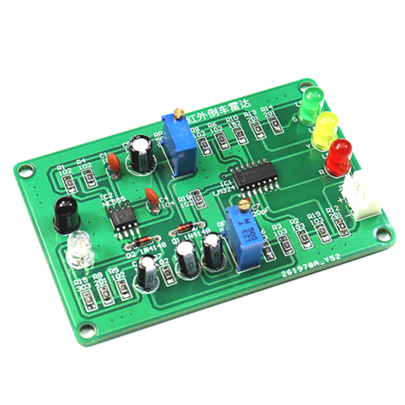
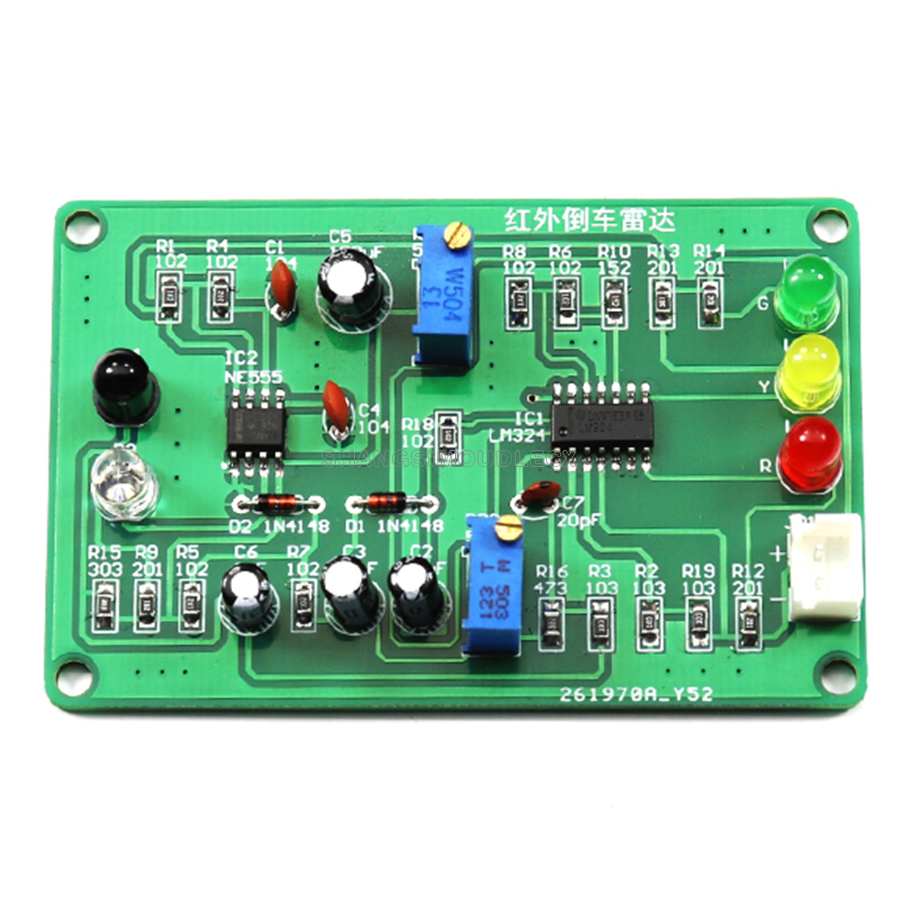
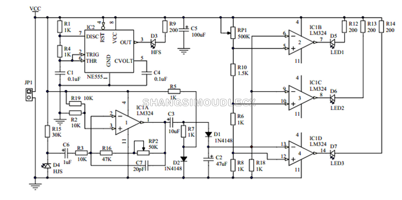
2. The infrared reversing radar is composed of multi-harmonic oscillation circuit, infrared signal transmitting and receiving circuit, infrared signal amplifying and voltage comparison circuit, which has the characteristics of simple circuit, low cost and stable circuit work.
3. Time base circuit NE555 and surrounding components form a multi-harmonic oscillator to generate infrared wave signal, which is output by IC2 pin 3 and drive infrared transmitter tube HFS to transmit infrared signal.
4. Exquisite and compact appearance
5. Widely used in a variety of distance measurement occasions
Supply voltage: DC9V (DC power supply)
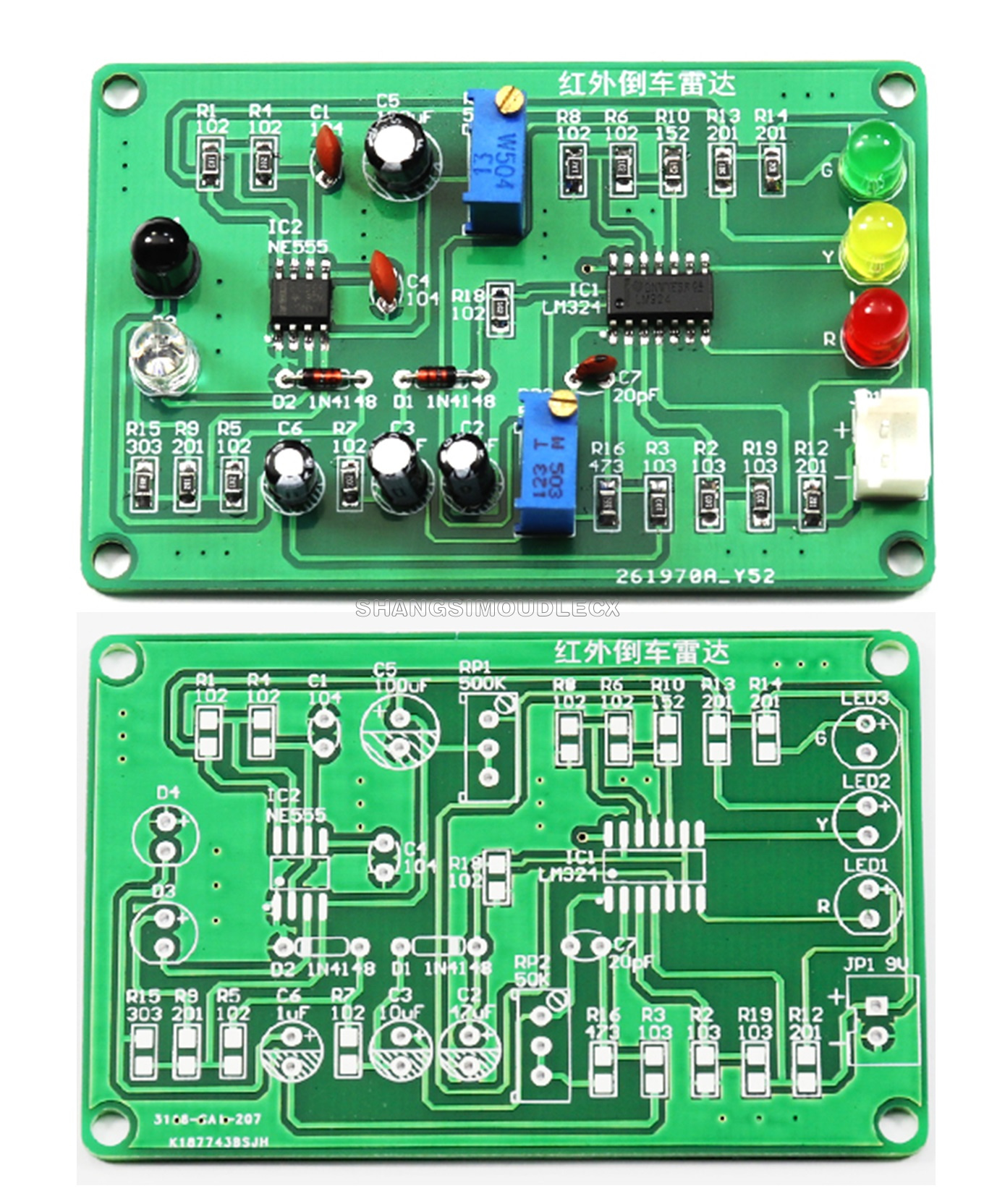
Board size: 70*45mm
Soldering and component installation is the key to success, please use high quality solder, solder joints should be bright without false solder leakage, components should not be installed incorrectly, follow a certain order in the production, install part of the components and then install another part. Start with the installation of short components, such as resistors, and then install high components. Chip notch position against the board with a notch mark.
1, installation of chip resistors, resistors do not distinguish between positive and negative;
2, the installation of NE555 \ LM324, first solder a pin to fix the chip, in the other pins to the tin soldering completed. Pay attention to the installation direction of the chip, mark the point to align the mark point location installation.
3, the installation of 1N4148, black circle position aligned with the board black mark position.
4、The porcelain chip capacitor has no positive and negative polarity. Electrolytic capacitor long foot is positive, corresponding to the position of the circuit board with positive.
5, light-emitting diode and infrared transmitting and receiving diode long foot is positive, corresponding to the location of the circuit board with positive.
After installation, check again whether the components are installed wrong, whether the welding is good, and then access to 9V power supply, pay attention to the positive and negative power supply can not be connected to the reverse.
In the case that there is no obstruction above the infrared transmitter tube and receiver tube, adjust RP1 to make the LED3 on the circuit board light up, and then adjust RP1 in the opposite direction to make the LED3 just go out. Then use a reflective object (you can use white paper) to gradually approach the position between the infrared transmitter tube and the infrared receiver tube from a distance, and as the distance approaches, LED3 to LED1 lights up in turn, and the infrared reversing radar is pressed and installed.
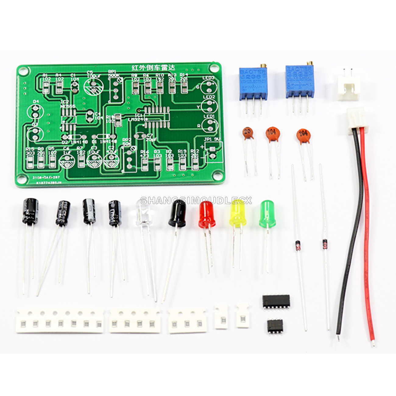
1 x DIY kit
We appreciate your feedback very much. As it will motivate us do better. If you have any questions with our goods or service, Please kindly contact us firstly before leaving negative feedback. Thank you in advance
1. All merchandise will be carefully test before shipping. We will try our best to avoid any quality problem.
2. We promise warranty for quality in one year and we will repair it free of charge. The returning shipping should be paid by customer.
3. If you are not satisfied with the product, Please contact us. We'll provide you a satisfying solution.
1.Normmly we will send the goods within 1-3 working days after your payment is verified .
2.Please check if the goods are in good condition and sign before the delivery man leaves.If you find the product is lost or damaged on the way. Please take photo and let the delivery men confirm it. Then we will help you let the shipping company compensate you.