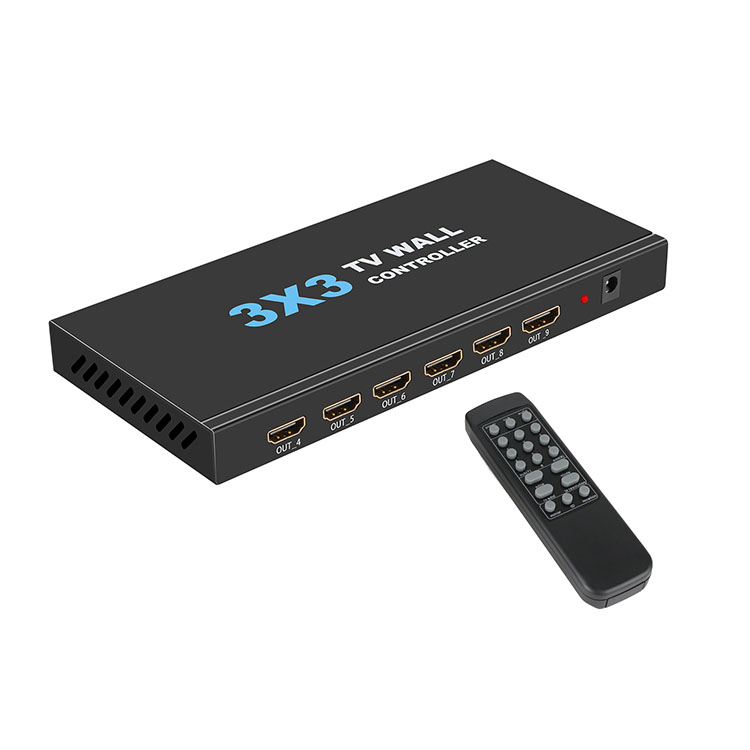
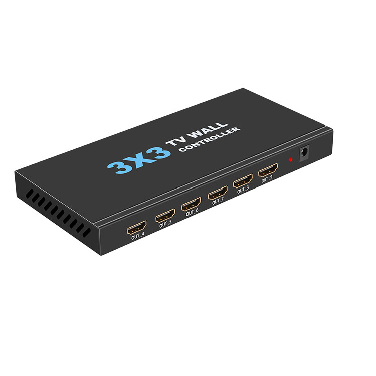
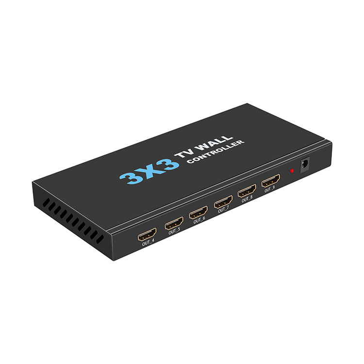
4K HDMI 3X3 Multi-screen Splicing TV Splicing Box Processor Support Dual Cascade 3x4/4x3/4x4
Features:
l High quality for professional use
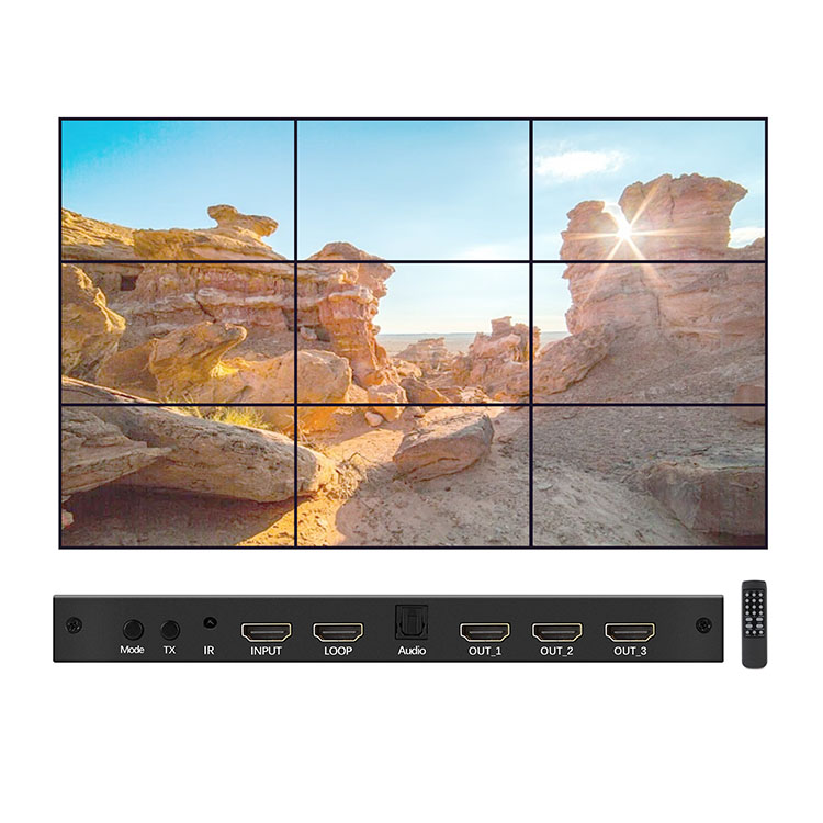
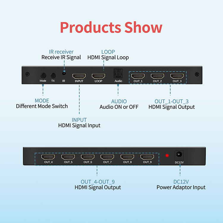
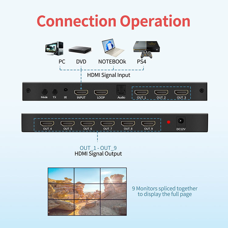
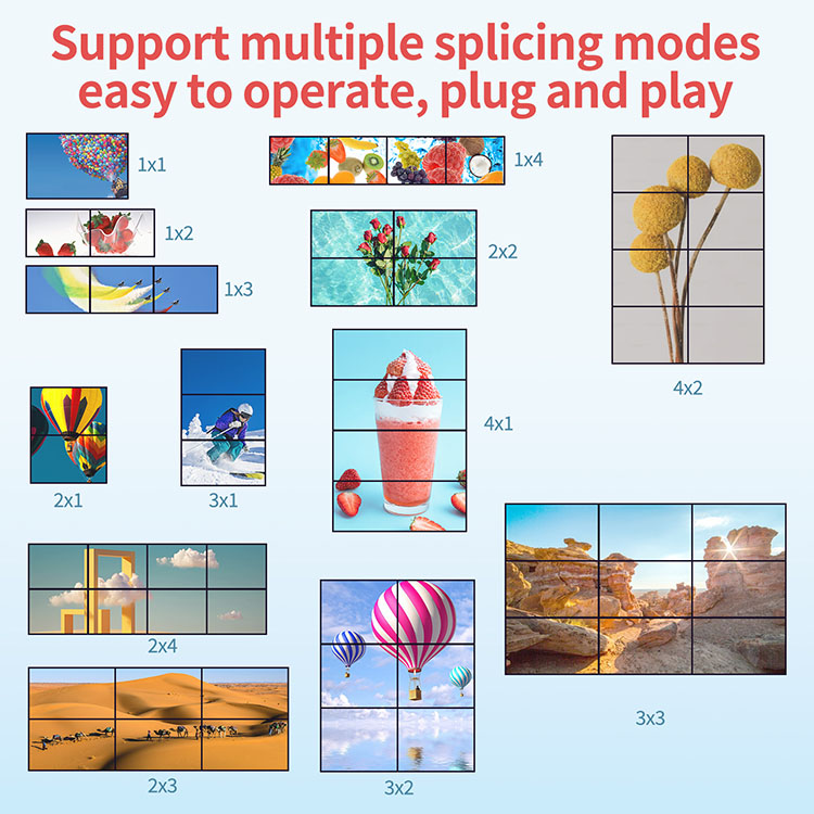
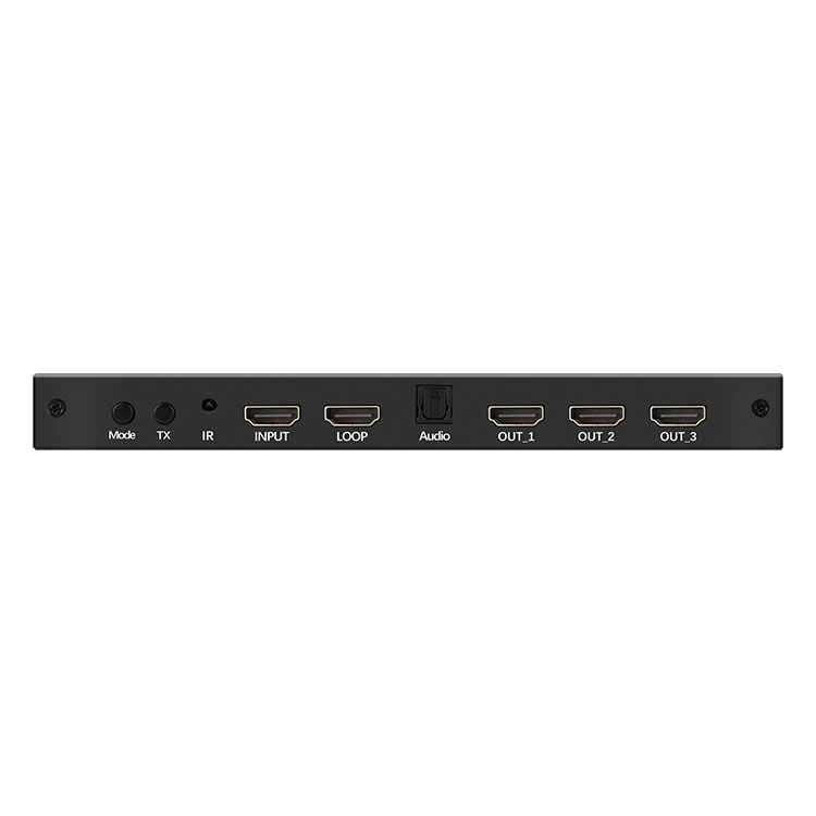
l This 3X3 Splicer supports 1 HDMI input and 9 HDMI output. The main function of the Splicer is to divide a full HDMI image into 9 blocks and distribute them to 9 video displays, complete with 9 HDMI HD video display units to form a large dynamic image screen. Supports multiple splicing modes, supports cascading
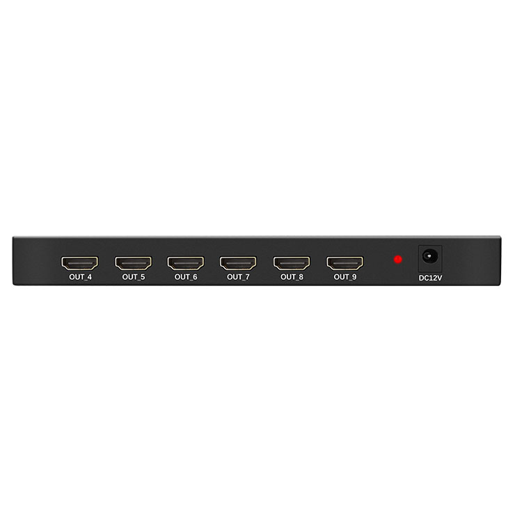
l 9-way HDMI output
l 3840x2160P30HZ input and output are compatible
l Multiple splicing support, easy operation, Plug and play
l Support 2 machine sub-cascade
Specification:
l Types (Optional): American Standard, European Standard, Australian Standard, British Standard
l Working Temperature: 0~40
l Power Consumption: 5W
l Size: 205x97x20mm
l Power Interface: AC Power Interface
l Live View: 4K
l Video Output Interface Type: HDMI
l Audio Access: SPDIF
l Video Input Interface Type: HDMI
l Number of Audio Inputs: 1
l Supply Voltage: 12V1A
l Audio Input Connector Type: Optical
l Number of Video Output Connectors: 11
l Quantity: 1 Set
Package:
l 1x 3x3 Splicer, 1x Power Adapter, 1x User Manual, 1x Remote Control
Note:
l HDMI cable must use 19 + 1 full needle of wire
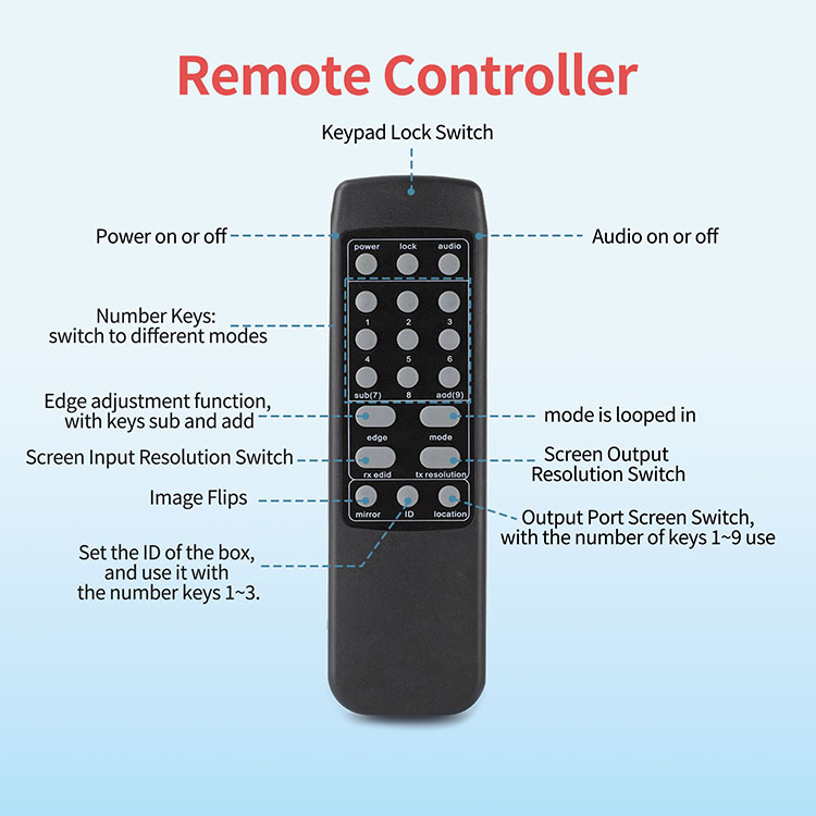
l The use of image flipping (each image can be flipped independently) : Step 1, press the remote control“Mirror” button, wait for the OSD in the upper left corner of the image to display“Mirror”; Step 2, use the number button to operate, for example, you want to flip the sixth screen, you press the number“6” button. When you're done, remember to press the“Mirror” button again to exit the operation
l Switch the output port screen: first, press the remote control“Location” button, wait for the OSD in the upper left corner of the screen to show“Location”; second, use the digital keys to operate, for example, you want to select the 6th screen output, you press the number“6” button. When you're done, remember to press the“Location” button again to exit the operation
l when two machines cascade, pay attention to the following points: the machine connected to the signal source is set to ID1, the operation steps: the remote control is aimed at the remote control receiving position of this machine (the machine is printed on the“IR” position) , first press the“ID” button, release, then press the number“1” button, at this time, OSD display“ID1”, the operation was successful; another machine set to ID2, operation Steps: the remote control at the receiving position of the remote control of this machine (the machine is printed on the“IR” part) , first press the“ID” button, release, then press the number“2” button, at this time, OSD display“ID2”, Operation Success; key lock“Lock” use: if you want to operate the ID1 machine, must first ID2 machine lock. The operation mode is to use the remote control to aim at the remote control receiving position of ID2(the machine is printed on the“IR” part) , press“Lock”, at this point all ID2 machine output screen in the upper left OSD display will appear a lock lock icon, the operation was successful. If you want to operate the ID2 machine, you must first lock the ID1 machine, the same operation.