


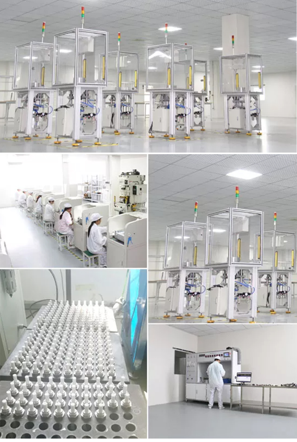
一一Factory Photo一一
一一Sale Policy一一
Payment一Accept multi-way payment
We accept Credit card, Debit card, Apple Pay, Google Pay and PayPal.
Shipping一US NJ Warehouse Fast shipping
We usually ship within 1~2 business day after receiving your payment.
Time of delivery:
US: About 1-6 business days
Returns一30 Days Free Return
We're confident in the product we sell.
But sometimes the item will be damaged during the transit as which rough and tough and out of our control.
If your item is defective or damaged when you received it, Pls kindly let us know asap.
Take a photos of the damaged items to us,once we confirmed it,we will give you satisfied solution.We can resend or refund once we confirmed.
一一About Us一一
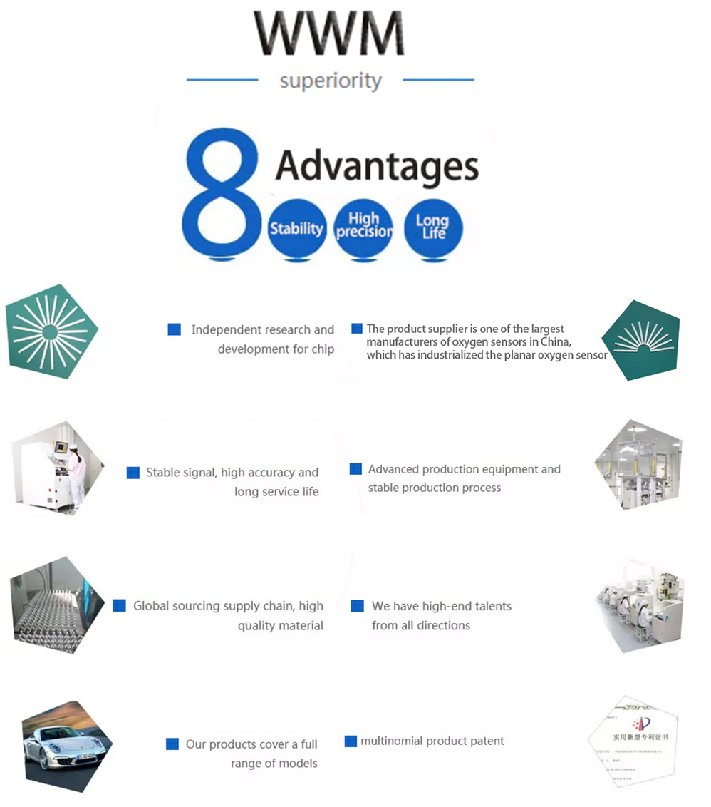
Delivering high-quality automotive oxygen sensors to consumers
WWM Technology Co., Ltd. is a company specializing in finding high quality automotive oxygen sensors and nitrogen oxygen sensors for you. The suppliers of our products are from Wuhan, China. They develop and produce various types of oxygen sensors such as concentration type, limiting current type, wide-range type, etc., covering all gasoline, diesel and hybrid engine models. requirements, to meet the needs of domestic and foreign users from OEM matching to spare parts market.
The company always regards "Delivering high-quality automotive oxygen sensors to consumers" as the goal of struggle, abides by the development mission of "science and technology leads quality to create", and follows the enterprise spirit of "creating value and realizing value".一一Factory Photo一一
Q: Why does the oxygen sensor have false alarm, after installation ?
A: The clearing of the errors can be obtained on most systems when the vehicle battery is disconnected for at least 60 seconds. The assignment of the new sensor parameters is done automatically when the errors are cleared, but in some systems a short adapting tour is required. In this case the vehicle has to be driven on the road for some 10-15 minutes, in order to have the ECU adapt itself to the new sensor.
Q: How do I know the O2 sensor is good or not ?
A: The only way to know if the O2 sensor is functioning normally is to check its responsiveness to changes in the air/fuel mixture, by Voltage Measurement or Waveform Simulation.
Q:How should I install oxygen sensor ?
A: The following is the installation instructions: Use the correct part number as listed in the application catalogue ,Do not use sensor if i has been dropped ,Remove protection cap just prior to installation;
Firstly install sensor body ensuring lead wire is not twisted or bent , Do not use impact wrench or socket type wrench to install sensor ,M18 sensors - install finger tight then 1/2-3/4 turn with a wrench (35-45Nm) ;
Then connect and route lead wire as originally installed , Do not allow lead wire to touch exhaust manifold or any other hot component ,Do not apply any substances (especially oil or grease) to connector sensor ,Do not use leaded fuels,silicone or metal based additives.
Q:How many oxygen sensors are on today's engines?
A: It depends on the model year and type of engine. On most four and straight six cylinder engines, there is usually a single oxygen sensor mounted in the exhaust manifold. On V6, V8 and V10 engines, there are usually two oxygen sensors, one in each exhaust manifold. This allows the computer to monitor the air/fuel mixture from each bank of cylinders.
On later model vehicles with OBD II (some 1993 and '94 models, and all 1995 and newer models), one or two additional oxygen sensors are also mounted in or behind the catalytic converter to monitor converter efficiency. These are referred to as the downstream O2 sensors, and thee will be one for each converter if the engine has dual exhausts with separate converters.
Q:How are the oxygen sensors identified on a scan tool?
A: When displayed on a scan tool, the right and left upstream oxygen sensors are typically labeled Bank 1, Sensor 1 and Bank 2, Sensor 1. The Bank 1 sensor will always be on the same side of a V6 or V8 engine as cylinder number one.
On a scan tool, the downstream sensor on a four or straight six cylinder engine with single exhaust is typically labeled Bank 1, Sensor 2. On a V6, V8 or V10 engine, the downstream O2 sensor might be labeled Bank 1 or Bank 2, Sensor 2. If a V6, V8 or V10 engine has dual exhausts with dual converters, the downstream O2 sensors would be labeled Bank 1, Sensor 2 and Bank 2, Sensor 2. Or, the downstream oxygen sensor might be labeled Bank 1 Sensor 3 if the engine has two upstream oxygen sensors in the exhaust manifold (some do to more accurately monitor emissions).It's important to know how the O2 sensors are identified because a diagnostic trouble code that indicates a faulty O2 sensor requires a specific sensor to be replaced. Bank 1 Sensor 1 might be the back O2 sensor on a transverse V6, or it might be the one on the front exhaust manifold. What's more, the O2 sensors on a transverse engine might be labeled differently than those on a rear-wheel drive application. There is not a lot of consistency as from one vehicle manufacturer to another as to how O2 sensors are labeled, so always refer to the OEM service literature to find out which sensor is Bank 1 Sensor 1 and which one is Bank 2 Sensor 1. This information can be difficult to find. Some OEMs clearly identify which O2 sensor is which but others do not. If in doubt, call a dealer and ask somebody in the service department.
Q:How does a downstream O2 sensor monitor converter efficiency?
A: A downstream oxygen sensor in or behind the catalytic converter works exactly the same as an upstream O2 sensor in the exhaust manifold. The sensor produces a voltage that changes when the amount of unburned oxygen in the exhaust changes. If the O2 sensor is a traditional zirconia type sensor, the voltage output drops to about 0.2 volts when the fuel mixture is lean (more oxygen in the exhaust). When the fuel mixture is rich (less oxygen in the exhaust), the sensor's output jumps up to a high of about 0.9 volts. The high or low voltage signal tells the PCM the fuel mixture is rich or lean.
On some newer vehicles, a new type of Wide Ratio Air Fuel (WRAF) Sensoris used. Instead of producing a high or low voltage signal, the signal changes in direct proportion to the amount of oxygen in the exhaust. This provides a more precise measurement for better fuel control. These sensors are also called wideband oxygen sensors because they can read very lean air/fuel mixtures.The OBD II system monitors converter efficiency by comparing the upstream and downstream oxygen sensor signals. If the converter is doing its job and is reducing the pollutants in the exhaust, the downstream oxygen sensor should show little activity (few lean-to-rich transitions, which are also called "crosscounts"). The sensor's voltage reading should also be fairly steady (not changing up or down), and average 0.45 volts or higher.
If the signal from the downstream oxygen sensor starts to mirror that from the upstream oxygen sensor(s), it means converter efficiency has dropped off and the converter isn't cleaning up the pollutants in the exhaust. The threshold for setting a diagnostic trouble code (DTC) and turning on the Malfunction Indicator Lamp (MIL) is when emissions are estimated to exceed federal limits by 1.5 times. See Troubleshooting a P0420 Catalyst Code for more info about converter problems.
If converter efficiency had declined to the point where the vehicle may be exceeding the pollution limit, the PCM will turn on the Malfunction Indicator Lamp (MIL) and set a diagnostic trouble code. At that point, additional diagnosis may be needed to confirm the failing converter. If the upstream and downstream O2 sensors are functioning properly and show a drop off in converter efficiency, the converter must be replaced to restore emissions compliance. The vehicle will not pass an OBD II emissions test if there are any converter codes in the PCM.
Q:What's the difference between a "heated" and "unheated" oxygen sensor?
A: Heated oxygen sensors have an internal heater circuit that brings the sensor up to operating temperature more quickly than an unheated sensor. An oxygen sensor must be hot (about 600 to 650 degrees F) before it will generate a voltage signal. The hot exhaust from the engine will provide enough heat to bring an O2 sensor up to operating temperature, but it make take several minutes depending on ambient temperature, engine load and speed. During this time, the fuel feedback control system remains in "open loop" and does not use the O2 sensor signal to adjust the fuel mixture. This typically results in a rich fuel mixture, wasted fuel and higher emissions.
By adding an internal heater circuit to the oxygen sensor, voltage can be routed through the heater as soon as the engine starts to warm up the sensor. The heater element is a resistor that glows red hot when current passes through it. The heater will bring the sensor up to operating temperature within 20 to 60 seconds depending on the sensor, and also keep the oxygen sensor hot even when the engine is idling for a long period of time.
Heated O2 sensors typically have two-three or four wires (the extra wires are for the heater circuit). Note: Replacement O2 sensors must have the same number of wires as the original, and have the same internal resistance.
The OBD II system also monitors the heater circuit and will set a trouble code if the heater circuit inside the O2 sensor is defective. The heater is part of the sensor and cannot be replaced separately, so if the heater circuit is open or shorted and the problem is not in the external wiring or sensor connector, the O2 sensor must be replaced.
Oxygen Sensor Locations
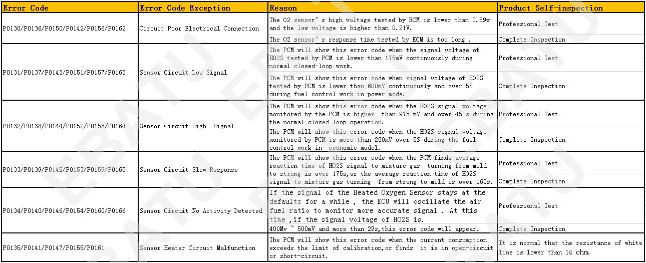
When troubleshooting oxygen sensor problems with a scan tool, you may find a diagnostic trouble code for one of the O2 sensors. The code displayed on your scan tool will indicate the type of fault, and identify one of the oxygen sensors by its position in the exhaust system.
The oxygen sensor's location will be identified by position (sensor 1, sensor 2 or sensor 3), and by cylinder bank (bank 1 or bank 2).
Most late model engines have multiple oxygen sensors, so which one is sensor 1, 2 or 3, and how do you know which cylinder bank is 1 or 2?
On straight four and six cylinder engines, there is only one bank of cylinders. So all of the oxygen sensors will be bank 1. The oxygen sensor or Air/Fuel sensor closest to the engine in the exhaust manifold will always be Sensor 1. The O2 sensor located in or behind the catalytic converter will be Sensor 2.
The location of the number one cylinder on import engines will vary depending on the year/make/model. One way to find number one cylinder so you can identify bank 1 is to look at the ignition system. If it has a distributorless ignition system (DIS) or a coil-on-plug (COP) ignition, the plug wires or coils may have lettering or marking indicating the cylinder numbers.
If a V6, V8 or V10 engine has dual exhausts with dual converters, the downstream O2 sensors would be labeled Bank 1, Sensor 2 and Bank 2, Sensor 2. Or, the downstream oxygen sensor might be labeled Bank 1 Sensor 3 if the engine has two upstream oxygen sensors in the exhaust manifold (some do to more accurately monitor emissions).
On V6 and V8 engines, Sensor 1 will always be on the SAME side as the Number ONE cylinder in the engine's firing order.
On a GM front-wheel drive car or minivan with a transverse (sideways) mounted engine, the number one cylinder is on the front side of the engine (closest to the radiator) on the right (passenger side) of the engine.
On a Chrysler front-wheel drive car or minivan with a transverse (sideways) mounted engine, the number one cylinder is on the back side of the engine (closest to the firewall) on the right (passenger side) of the engine (like a Ford).