Without battery
Product introduction:
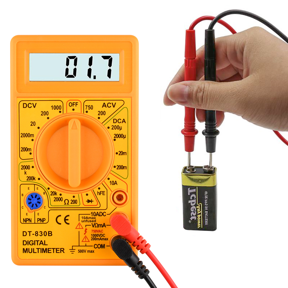
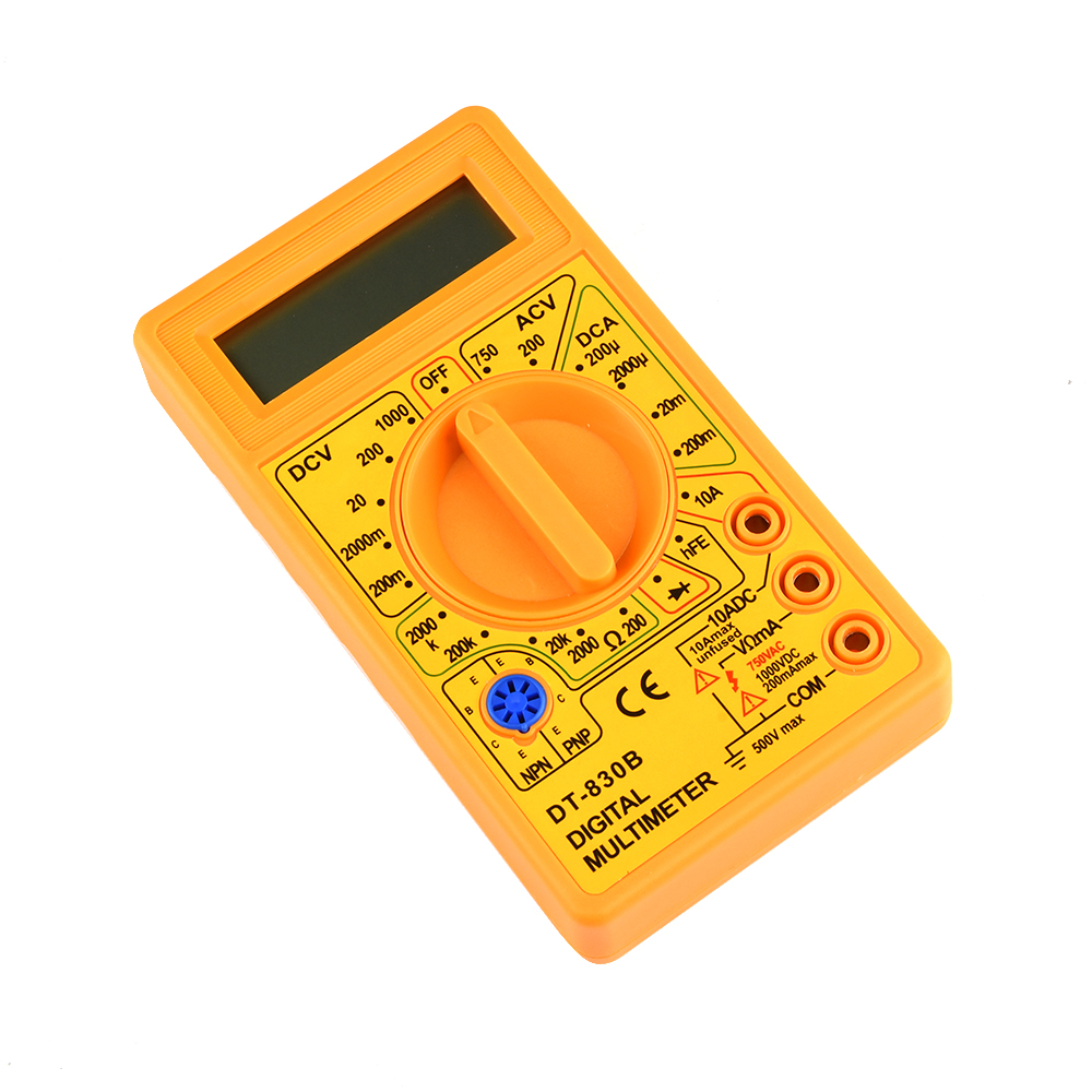
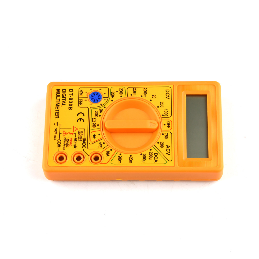
The DT830 digital multimeter is a three-and-a-half-digit LCD display small digital multimeter. It can measure AC, DC voltage and DC current, resistance, transistor β value, diode conduction voltage and circuit short circuit, etc. A rotary band switch can change the measurement function and range, with a total of 19 levels. The maximum display value of this multimeter is ±1999, which can automatically display "0" and polarity, and display "1" or "-1" when overloaded, and the diode gear for short-circuit check.
One. Technical characteristics
1. Measuring range
⑴ AC and DC voltage (AC frequency is 45Hz~500Hz); DC ranges are 200mV, 2000mV, 20V, 200V and 1000V respectively; AC ranges are 200V and 750V respectively; DC accuracy is ±(0.8% of reading + 2 words ) Below, the AC accuracy is ± (1% of reading + 5 words); the input impedance, the DC range is 10MΩ, and the AC range is 10MΩ, 100PF.
⑵ DC current The measuring ranges are 200μA, 2000μA, 20mA, 200mA and 10A. The DC accuracy is ± (1.2% of reading + 2 digits), and the maximum voltage load is 250mV.
⑶ Resistance: The ranges are respectively: 200Ω, 2000Ω, 20kΩ, 200kΩ, and 2000kΩ. The accuracy is ± (2.0% of reading + 3 words).
⑷ Diode conduction voltage: The range is 0~1.5V, and the test current is 1mA±0.5mA.
⑸ Triode β value detection: The test conditions are: VCE=2.8V, IB=10μA.
⑹ Short circuit detection:
Test circuit resistance<20Ω±10Ω
2. Sampling time:
T S = 0.4S.
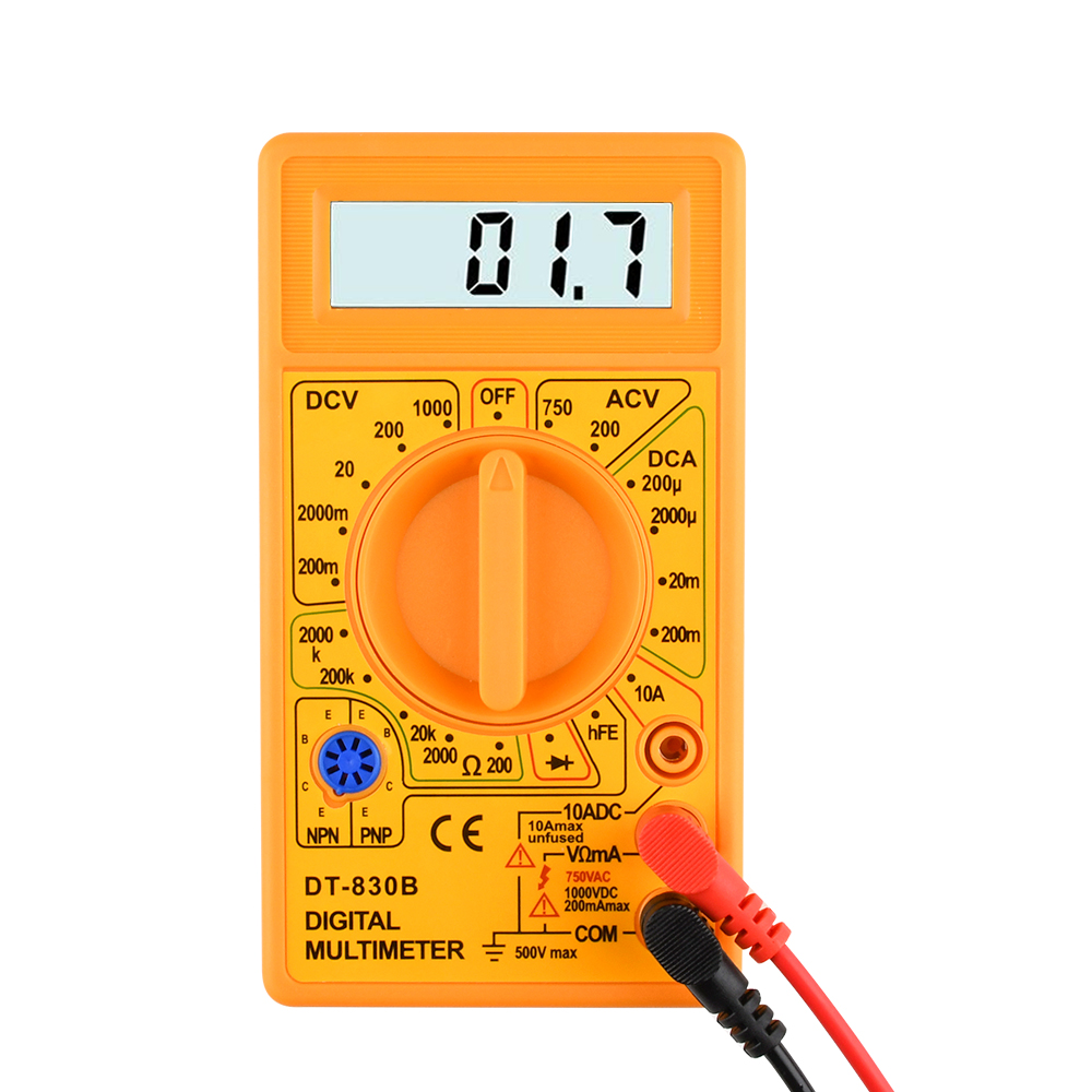
Two. Panel and operating instructions
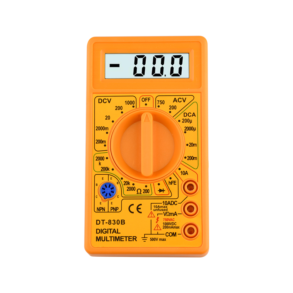
1. monitor
Three and a half digital LCD display
2. switch
Press it to turn on the power, and turn it off when not in use.
3. Capacitance measuring socket
This watch has no capacitance test function.
4. Function range switch
Choose different measurement functions and ranges.
5. 10A current jack (cannot measure current greater than 10A)
When measuring AC and DC currents greater than 200mA and less than 10A, the red test lead should be inserted into this 10A current jack.
6. Current jack
When measuring AC and DC currents less than 200mA, the red test lead should be inserted into this current jack.
7. V/Ω jack
When measuring AC and DC voltage, resistance, diode conduction voltage and short-circuit detection, the red test lead should be inserted into this V/Ω jack.
8. The black test lead from the “COM” jack of the grounding common terminal is always inserted into this grounding jack.
9. Beta test socket
Insert the collector, base, and emitter of the transistor under test into the "C", "B", and "E" jacks respectively, and pay attention to distinguish whether the transistor is an NPN type or a PNP type.
three. Instructions
1. ready
Press the power switch and observe whether the LCD display is normal and whether there is a battery shortage sign. If there is, replace the battery first.
2. use
(1) For the measurement of DC current
select the appropriate current measurement range and the insertion hole of the red test lead according to the size of the measured current. When measuring DC, the red test lead touches the high end of the voltage and the black test lead touches the end of the low voltage. The forward current flows from the red test lead. When it flows into the multimeter, and then flows out from the black test pen, when the current to be measured is not clear, first use the largest range to measure, and then gradually reduce the range to accurately measure.
(2) Measurement of AC and DC voltage
Insert the red test lead into the "V/Ω" jack, and select the appropriate voltage measurement range according to the voltage. The black test lead touches the "ground" end of the circuit, and the red test lead touches the point to be measured in the circuit. Special attention should be paid to the fact that the frequency of AC voltage measurement by digital multimeter is very low (45~500Hz), and the voltage amplitude of medium and high frequency signals should be measured by AC millivoltmeter.
(3) Resistance measurement
Insert the red test lead into the "V/Ω" jack, select the appropriate resistance measurement range according to the size of the resistance, touch the red and black test leads to the two ends of the resistance, and observe the reading. In particular, when measuring on-circuit resistance (resistance on the circuit board), the power of the circuit should be turned off first to avoid jitter in the reading. It is forbidden to measure current or voltage with resistance gear (especially AC 220V voltage), otherwise it is easy to damage the multimeter. In addition, the resistance profile can also be used to qualitatively judge the quality of the capacitor. First, short-circuit the two poles of the capacitor (touch the two poles with one test lead at the same time to discharge the capacitor), then touch the two test leads of the multimeter to the two poles of the capacitor respectively, and observe the displayed resistance reading. If the resistance reading displayed at the beginning is very small (equivalent to a short circuit), and then the capacitor begins to charge, the displayed resistance reading gradually increases, and the resistance reading displayed at the end becomes "1" (equivalent to an open circuit), indicating that the capacitor is Ok. If you follow the above steps and the displayed resistance reading remains the same, it means that the capacitor has been damaged (open circuit or short circuit). Special attention should be paid to the selection of the appropriate resistance range based on the size of the capacitance. For example, 47μF uses 200k gear, while 4.7μF uses 2M gear and so on.
(4) Diode conduction voltage detection
In this position, the red test lead is connected to the internal positive power supply of the multimeter, and the black test lead is connected to the internal negative power supply of the multimeter. The connection of the two test leads and the diode is shown in Figure 1. If the connection is measured according to Figure 1(a), the tested diode is forward-conducting, and the multimeter displays the forward-conducting voltage of the diode in mV. Generally, the forward voltage of a good silicon diode should be 500mV~800mV, and the forward voltage of a good germanium diode should be 200mV~300mV. If it displays "000", it means that the diode is short-circuited, and if it displays "1", it means that the diode is blocked in the forward direction. If it is measured according to Figure 1(b), it should display "1", indicating that the diode is reversely cut off. If it displays "000" or other values, it indicates that the diode has reversed breakdown. This file can also be used to judge the quality of the transistor and the identification of the pins. When measuring, first connect a test lead to a certain pin, and then connect the other test lead to the other two pins. If the test leads are both conductive or non-conductive, then Change two test leads and test again, and both times are not conducting or conducting, then it can be determined that the transistor is good, and it can be determined that the identified pin is the base of the transistor. If the red test lead is connected to the base electrode and the black test lead is connected to the other two electrodes respectively, both are conductive, it means that the transistor is of NPN type, otherwise, it is of PNP type. Finally, compare the magnitude of the forward conduction voltage of the two PN junctions. The larger reading is the be junction, and the smaller reading is the bc junction, so both the collector and the emitter are identified.
(5) Triode value β test First
determine whether the transistor to be tested is NPN or PNP, and then correctly insert its pins into the corresponding type of test socket. Turn the function range switch to the β position, that is, you can read the β value directly from the display. "000" means that the transistor is broken.
Four. Precautions
1. Pay attention to the correct selection of range and red test lead socket. When measuring the unknown quantity, the range should be adjusted to the maximum first, and then adjusted from large to small, until it is suitable for this. If "1" is displayed, it means over-cut, and the range should be increased.
2. When not measuring, turn off the power at hand.
3. When changing the range, the test lead should be disconnected from the measured point.
4. When measuring current, avoid overloading.
5. It is not allowed to measure voltage with resistance file and current file
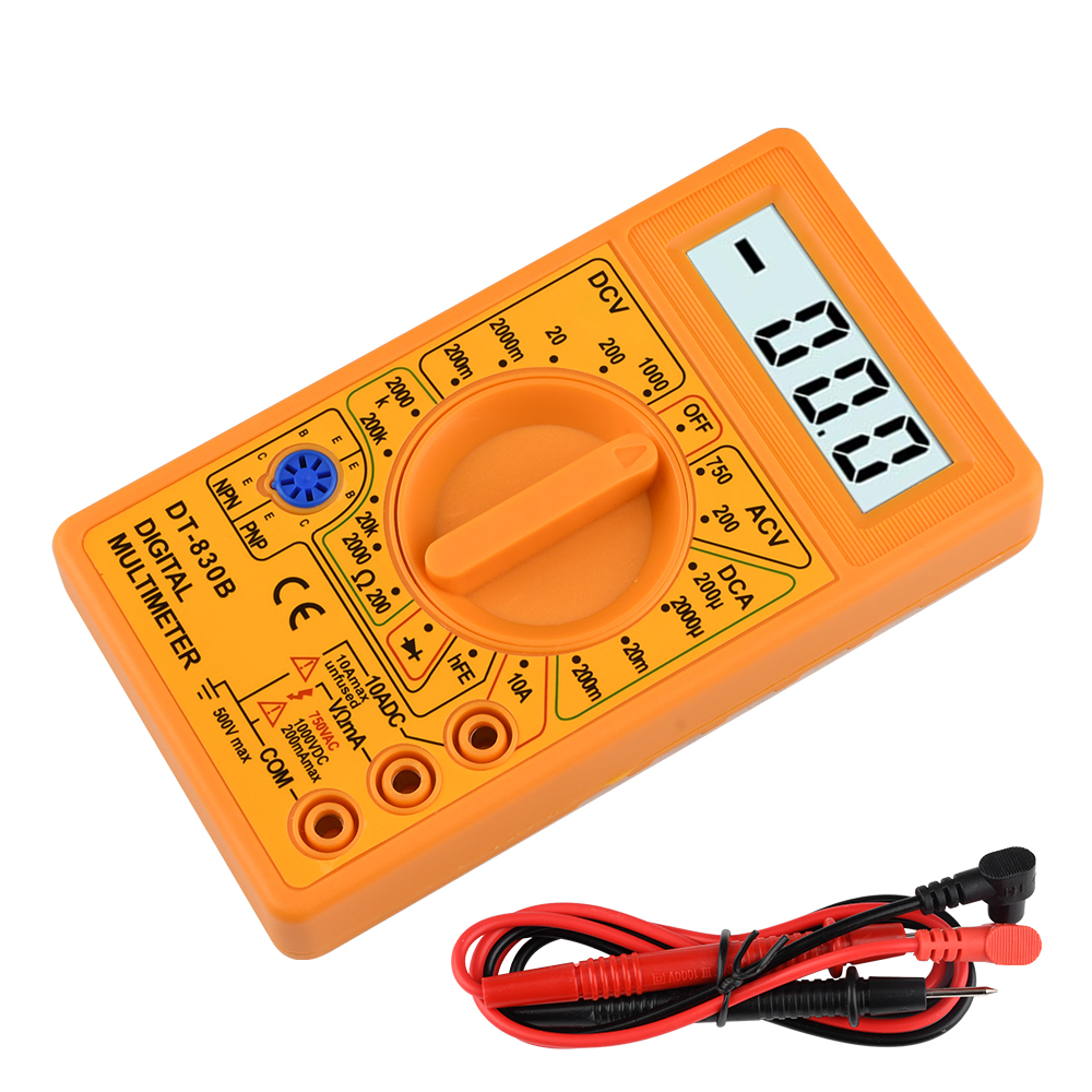
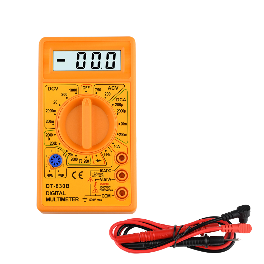
Package Included:
Multimeter x1 Test lead x1 (Without battery)