Ground Grid Regulated Power Supply( ±200VDC) PCB & DIY KIT & Finished Board
DIY KIT Project
To complete this project, high level knowledge of electronics and rich experience in terms of soldering and testing are required.
Due to time zone and language communication restrictions, we can only provide limited technical support, and you need to solve problems by yourself.
We do not provide information other than the product introduction page.
MOFI-Ground Grid Regulated Power Supply( ±200VDC) DIY KIT
high-voltage:
The high-voltage power supply uses MOSFET as pass transistors, which have a sense of tube sound characteristics but rejecting the rectification and regulation noise.
high-voltage soft-start feature is included which will take about 5 second to reach the designed voltage protecting the tube from any voltage shock.
low-pass filter prevents power noise from being introduced into the amplifier. Provide purer power supply .
Onboard heatsinks used which would allow the 2SK2700 to supply up to 0.1A continuous
More sustained currents are possible by using larger, offboard heatsinks.(2A)
heater –voltage:
heater -voltage soft-start feature for vacuum heater is included which will take about 5 second to reach the designed voltage(6.3v or 12.6v) protecting the tube from any voltage shock and extending life.
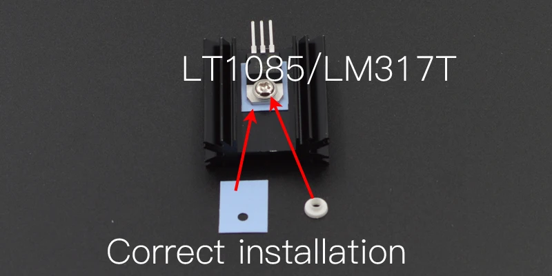
Onboard heatsinks used which would allow the LT1085CT to supply up to 1A continuous
More sustained currents are possible by using larger, offboard heatsinks.(2A)
PCB comes with component parameters for easy installation
Do not short the output terminal to discharge capacitor, otherwise it will damage the power board.
Product configuration
DIY kit: Contains the PCB and the components needed on the PCB, but does not include the power transformer.
Finished board: Based on the well-tested board on the standard version kit, we verified all key points' voltage, and used the signal generator and oscilloscope for analog waveform double verification. We will not use this board for listening test.
All finished pcbs are all carefully hand-soldered and fully tests, so the price is higher and less cost performance. Price-sensitive consumers but with have DIY ability are recommended to choose the kit.
DIY KIT Instructions
Since the PCB holes are plated through, you only need to solder the parts from the bottom of the board. Do not drill or enlarge the holes because that would damage the through-plating.
Clean both sides of the blank PCB with paper towel and isopropyl alcohol or electronics flux remover, then solder the components to the board, starting with the lowest profile parts. This means the resistors and zener diode. Then solder the small capacitors, small transistors, followed by the larger capacitors.
Make sure the correct part goes into each position on the circuit board. Measure each resistor with your multimeter to ensure it's the proper value.
Pay attention to the polarity of electrolytic capacitors, diodes, , transistors as well as the orientation.
Clean up the solder flux residue from the board with isopropyl alcohol (or electronics flux remover) and a brush.
Inspect all solder connections carefully, using a magnifying glass, to make sure there are no solder bridges or cold solder joints. Use a multimeter in ohms scale to check for short circuits.
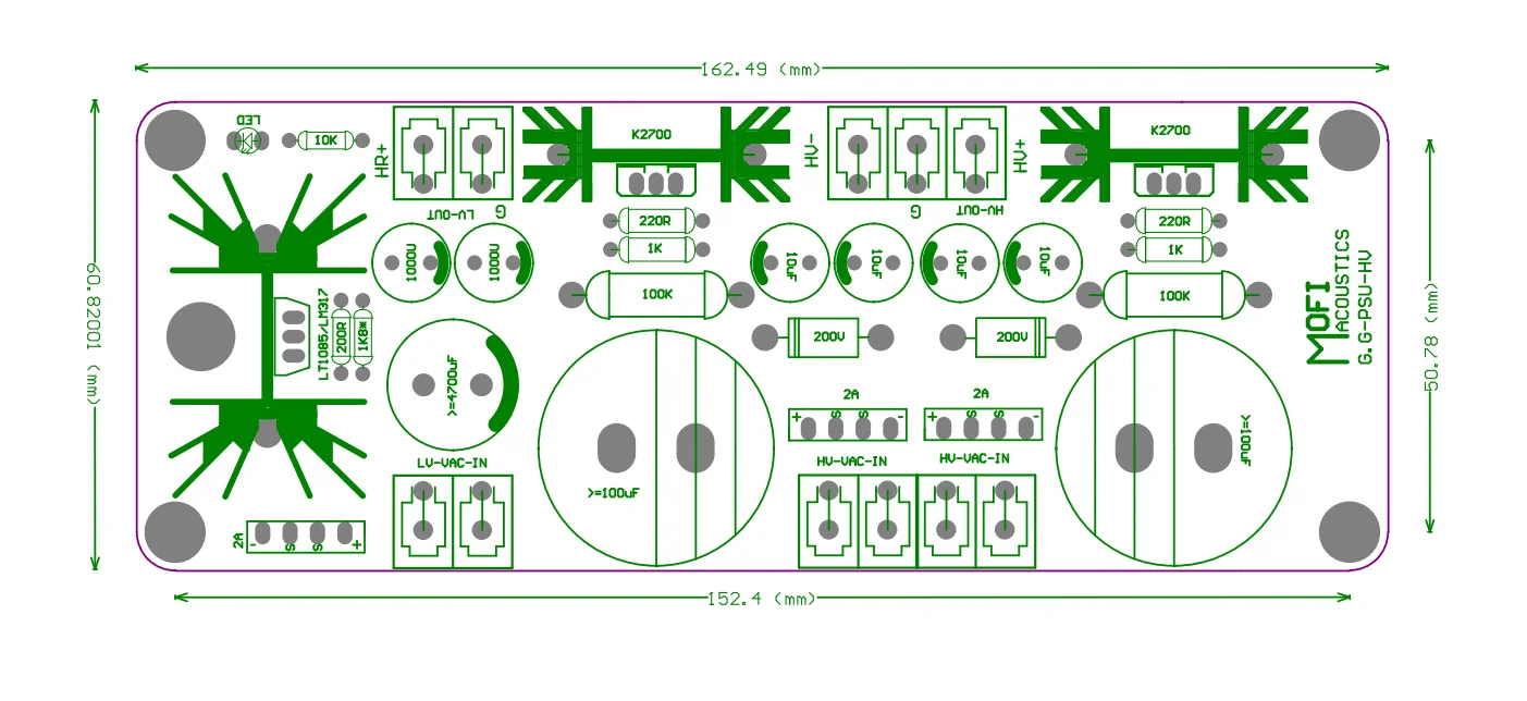
Parts list

