DIY KIT Project
To complete this project, high level knowledge of electronics and rich experience in terms of soldering and testing are required.
Due to time zone and language communication restrictions, we can only provide limited technical support, and you need to solve problems by yourself.
We do not provide information other than the product introduction page.
MOFI-PM14A Fully Discrete Fully Direct-Coupled Pre-Amplifier DIY KIT Project
-Summary
MOFI-PM14A Pre-Amplifier, It is based on the core circuit of theMarantz PM14A Pre-Amplifier.
-Tech highlights
Compared with the commonly reproduction of PM14A, we improved:
Using Two-stage buck regulator filter,Two low-pass filter prevents power noise from being introduced into the amplifier. Provide purer power supply (close to battery).
The high-voltage power supply uses MOSFET as pass transistors, which have a sense of tube sound characteristics but rejecting the rectification and regulation noise..
voltage soft-start feature is included which will take about 5 second to reach the designed voltage.
all-in-one design, single-point grounding, ground resistance is close to the 0.02 ohm resistance value, low noisedesign.
PCB is small and flexible, more suitable for all kinds of chassis installation.
More cost-effective sound modification plan.
Fully Discrete AMP.
Fully direct-coupled,This is a true DC amplifier. Care must be taken to ensure that the input source does not have DC offset at its output..
Product configuration
DIY kit: Contains the PCB and the components needed on the PCB, but does not include the power transformer .
Finished board: Based on the well-tested board on the standard version kit, we verified all key points' voltage, and used the signal generator and oscilloscope for analog waveform double verification. We will not use this board for listening test.
All finished pcbs are all carefully hand-soldered and fully tests, so the price is higher and less cost performance. Price-sensitive consumers but with have DIY ability are recommended to choose the kit.
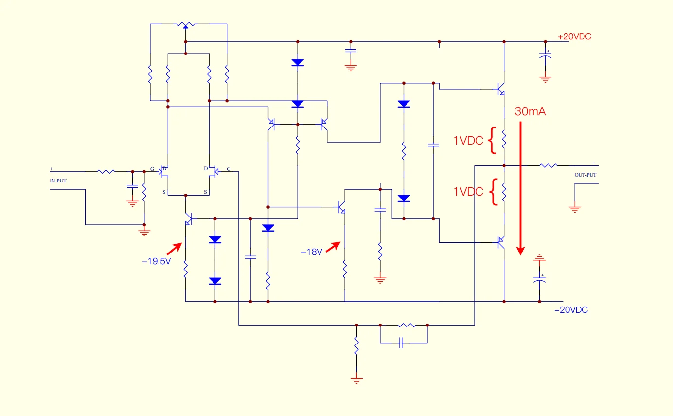
Schematic & key point of debugging
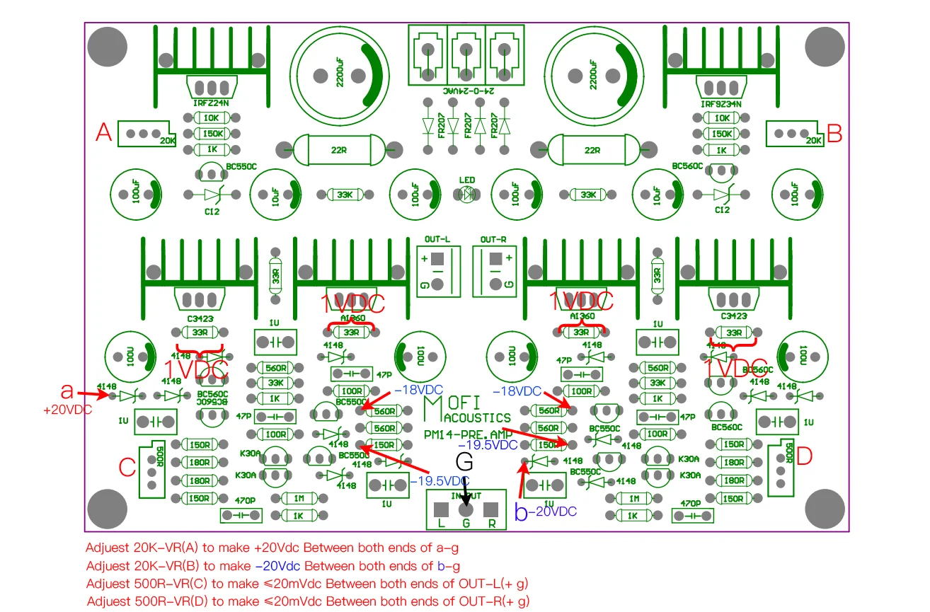
PCB comes with component parameters for easy installation.
We only refer the schematic of the amplification part of the circuit. If you need full circuit parameter, please read the component value with the PCB by yourself; we do not provide additionally.
please keep test point voltage close enough to it, +-20% is also permitted
DIY KIT Instructions
Since the PCB holes are plated through, you only need to solder the parts from the bottom of the board. Do not drill or enlarge the holes because that would damage the through-plating.
Clean both sides of the blank PCB with paper towel and isopropyl alcohol or electronics flux remover, then solder the components to the board, starting with the lowest profile parts.
Make sure the correct part goes into each position on the circuit board. Measure each resistor with your multimeter to ensure it's the proper value.
Clean up the solder flux residue from the board with isopropyl alcohol (or electronics flux remover) and a brush.
Inspect all solder connections carefully, using a magnifying glass, to make sure there are no solder bridges or cold solder joints. Use a multimeter in ohms scale to check for short circuits. As a minimum, you should verify that the V+ and V- DC inputs are not shorted to ground, or to each other, and that the output pad isn't shorted to ground. Correct any mistakes before proceeding to the next phase.

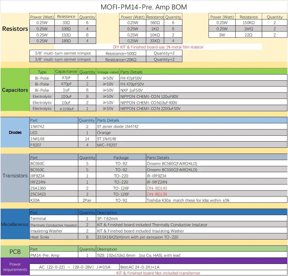
Parts list