DC 12V 24V Motor Controller Forward Reverse Manual

Power:Optional DC5V/DC12V/DC24V
Input Signal:Forward,Reverse,Positive limit,Reverse limit. [High level 4-26v( PNP sensor or contact switch) ]
Trigger logic:Forward,Reverse,Cyclic forward and reverse
Output action:
1.Motor blocked overcurrent stop 0-8A adjustable (2s do not trigger afterovercurrent)
2.Limit control (this direction does not trigger after limit)
Function:
(positive and reverse switch has 200mS delay)
1.Inching forwardor reverse
2.self-locking forward or reverse
3.power cycle forward and reverse

First, Function Settings:
【1】Power up the module
【2】Long press the setting key for 1 second to enter the mode setting, the mode indicator flashes ,the number of flashes corresponds to the mode, and short press the setting key to switch the mode(There are three modes, mode 1 to mode 3 cyclic switching).
【3】Long press the setting key again for 1 second to enter the current setting, and the current indicator flashes on ,the flashing times correspond to the current gear. Short press the setting key to switch the protection current
(the protection current is divided into 8 gears on average, the minimum in gear 1, the maximum in gear 8,it's the limit protection current 8A of the module, and the cycle switching from gear 1 to gear 8 ). The program control of the blocked current 1-8A can be set accurately and stably.
【4】Finally, press and hold the setting key for 1 second to save the setting. The module starts to work. The module power-off parameters are not lost and can be used directly.
Second, Output mode table :
No: Mode 1
Name : Inching forward rotation or reverse
Description : When there is a forward signal, the motor is forward; When there is a reversal signal, the motor is reversed; No forward signal, and no reverse signal, the motor stopped.
Remarks : After reaching the forward rotation limit, it can't turn forward again,When the reverse limitis reached, it can't be reversed again; The limit Signal has priority, and the limit is encountered during rotation the Signal will stop Immediately.
No: Mode 2
Name: Self-locking forward rotation or reverse
Description: The signal just needs to be triggered more than 20ms, Module self-locking runs all the time. Reverse signal encountered when turning forward, reverse immediately.
Remarks: Same as above Mode 1 remark
No: Mode 3
Name: Power-on cycle forward & reverse
Description: Power-on module will automatically trigger a forward rotation, when the motor runs to the forward rotation limit switch, the limit switch triggers the reverse signal, the motor reverses; the motor runs to the forward rotation limit switch, the limit switch triggers the forward rotation signal, and the motor rotates forward. Keep cycling.
(In this mode the limit switch is used to trigger the motor automatic forward and reverse rotation)
Remarks: To realize the function of mode 3, the output signal of the limit switch needs to be connected to forward and reverse trigger port of the motor.

No:1
Cases: Window lifter
Function: Adopts SPDT inching switch,which connects the two output signals of the switch to the forward rotation and reverse rotation trigger ports respectively, set the over-current gear to about the motor locked rotor current, the forward rotation signal is triggered, the glass rises to run, the glass rises to the position, the motor is locked, and the controller controls the motor to stop.
Remarks:After the forward rotation limit is triggered, the signal can no longer trigger forward rotation; After the motor over-current stops, the signal can trigger the forward rotation again.
No:2
Cases: Automatic split the glass door
Function: Glass sliding door The human body infrared detection module drives a SPDT relay module the common point of the relay module is connected to the high level, the normally open and normally closed are connected to the forward and reverse signal ports respectively, and the limit switch is connected to the limit signal port.
When the human body infrared detection module detects someone approaching, the output high-level trigger relay module is pulled in, the normally open point and common point are connected, the output high-level is output, the trigger module rotates forward, the signal port rotates forward, the motor rotates forward, reaches the limit point, the limit switch is triggered, and the motor stops. When the person leaves, the human body infrared detection module outputs low level, the relay is disconnected, the normally closed port outputs high level, the module reverse port is triggered, the motor reverses, the limit switch reaches the limit point, the motor stops and the door is closed.
Remarks: After the forward rotation limit is triggered, the signal can no longer trigger forward rotation.
No:3
Cases: Logistics lockers/ Automatic gate lifting rod/Home automatic cabinet/Automatic mixer
Function: The implementation process is similar to the above case process
Remarks: Auto-control, overcurrent protections

Note:
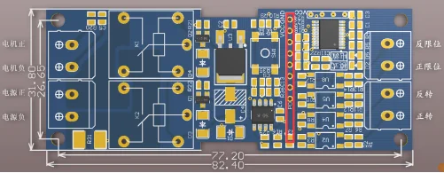
module size: 82.4 *31.8*18 mm (L/W/H),has four 3.2mm mounting holes and can be mounted using 3mm copper posts.
Same time,it also can be equipped with special a ABS plastic shell,which can be installed on 35mm U-shaped guide rail. The shell size: 88mm*37mm*59mm.

> Wireless remote control settings:(Wireless mode setting and learning)
1)Short press LK 1 time and the LED flashes 1 time .
After releasing the key for 1 second, the LED is always on. Set the working mode to 4-channel output Inching mode and enter the learning mode. Press any key on the remote control within 5 seconds to complete the learning. After the learning is successful, the LED goes out. If the remote control key is not pressed within 5 seconds, the LED also goes out and exits the learning mode.
2)Short press LK for 2 times, the LED flashes 2 times, and other same as 1)
3)Short press LK for 3 times, the LED flashes for 3 times, and other same as 1)
4)Short press LK for 4 times, LED flashes for 4 times, and other same as 1)
5)Short press LK for 5 times, LED flashes for 5 times, and other same as 1)
6)Short press LK for 6 times, LED flashes for 6 times, and other same as 1)
7)Short press LK for 7 times, the LED flashes for 7 times, and other same as 1)
8)Short press LK for 8 times, and the LED flashes for 8 times. After releasing the key, the LED goes out, that is, all saved states (code matching) are cleared, and the working mode is restored to the 4-way inching mode at the factory.
9)The factory default of the module is 4-way inching mode.
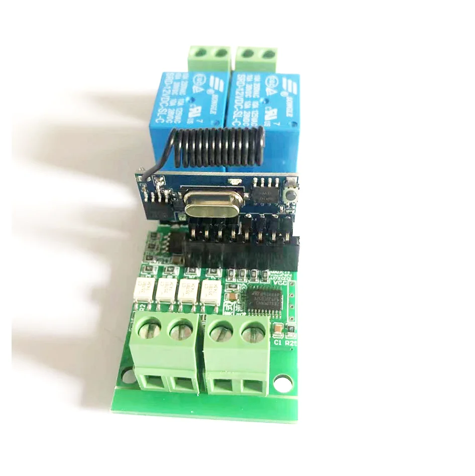
>Wireless receiver board ports description:
Pin name Description
GND Power negative
VCC power positive (typical +3.3V)
D0 first switch output, low level at normal times,
high level when controlled
D1 Second switch output...(as above)
D2 Third switch output.......(as above)
D3 fourth channel switch output...(as above)
LK external LED and key reuse pin, no external
connection can be suspended
PD hibernation pin (connected to VCC hibernation,unable
to receive signals after hibernation ; Grounding work)
GND Power negative
GND antenna ground
ANT antenna
>Wiring remote control pairing:
Power on the forward and reverse controller, short press the key on the wireless receiving board once, wait for the light is always-on on the wireless receiving board , and long press any key on the remote control until the light off , and the wireless setting is successful.
(combined with the below picture, especially the receiver board can't be inserted wrong ):

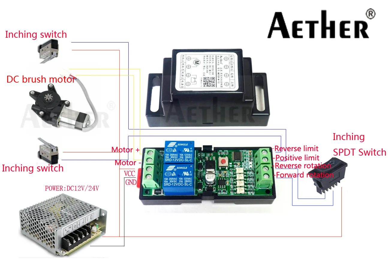
above wiring diagram is based on the control mode oflimit switch.It can also be controlled by locked rotor current(the limit switch can be connected or not).
END