
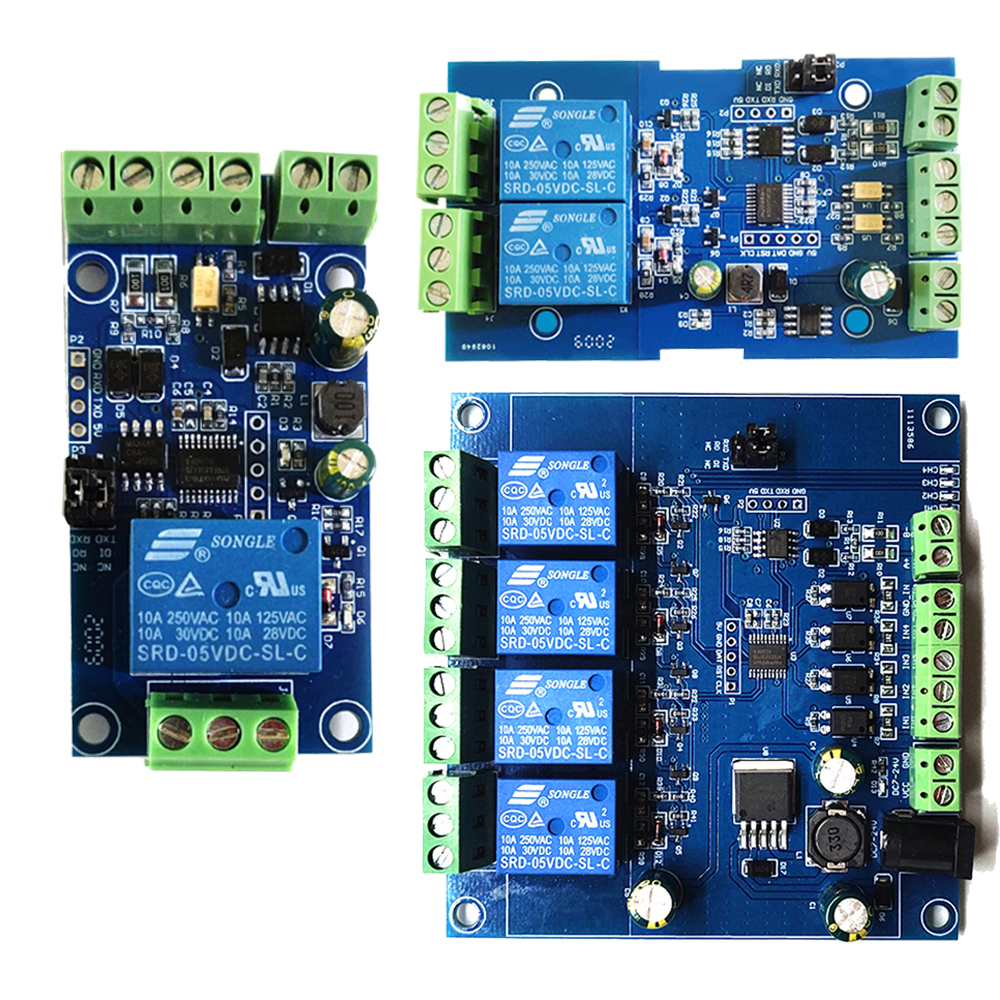
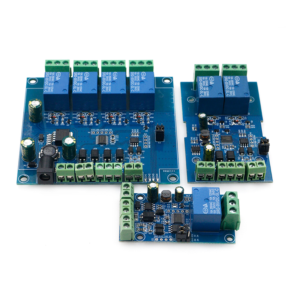
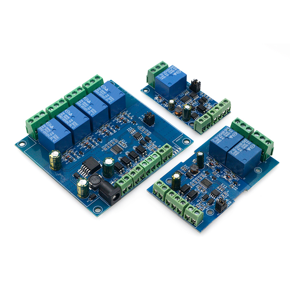
1 Channel
Single Modbus relay module is equipped with mature and stable 8-bit MCU and
RS485 level communication chip. RS485 communication using standard MODBUS RTU format
Communication protocol, which can realize 1 optical coupler input signal detection and 1 relay output, which can be used for digital
Word quantity detection or power control occasions.
Product parameter
1. Onboard mature and stable 8bit MCU and MAX485 level conversion chip
2. Communication protocol: support standard Modbus RTU protocol
3. Communication interface: support RS485/TTL UART interface
4. Communication baud rate: 4800/9600/19200, default 9600bps, support power-off save
6. Optocoupler input signal range: DC3.3-30V (this input cannot be used for relay control)
7. Output signal: relay switch signal, support manual, flash off, flash off mode, flash off/flash
The base number of the time delay is 0.1S, and the maximum flash-off/flash-off time can be set as
0xFFFF*0.1S=65535*0.1S=6553.5S
8. Device address: range 1-255, default 255, support power-off save
9. Onboard 1 way 5V, 10A/250V AC 10A/30V DC relay, can suck continuously
100,000 times, with diode effusion protection, short response time
10. On-board relay switch indicator
11.Supply voltage: DC7-24V, with input anti-reverse connection protection
Package included:
DC 7-24V Relay Module RS485/TTL1 Input And Output With Anti-reverse Protection
2 Channel
Description:
Dual ModbSU relay module is equipped with mature and stable 8-bit MCU and
RS485 level communication chip. RS485 communication using standard MODBUS RTU format
Communication protocol, can realize 2 input signal detection, 2 relay output, can be used for digital
In the case of volume detection or power control.
Product parameter
1. Onboard mature and stable 8bit MCU and MAX485 level conversion chip
2. Communication protocol: support standard Modbus RTU protocol
3. Communication interface: support RS485/TTL UART interface
4. Communication baud rate: 4800/9600/19200, default 9600bps, support power-off save
6. Optocoupler input signal range: DC3.3-30V (this input cannot be used for relay control)
7. Output signal: relay switch signal, support manual, flash off, flash off mode, flash off/flash
The base of the delay time is 0.1S, and the maximum flash-off/flash-off time can be set as
0xFFFF*0.1S-65535*0.1S=6553.5S
8. Device address: range 1-255, default 255, support power-off save
9. Onboard 1 way 5V, 10A/250V AC 10A/30V DC relay, can suck continuously
100,000 times, with diode effusion protection, short response time
10. On-board relay switch indicator
11.Supply voltage: DC7-24V, with input anti-reverse connection protection
Package Include:
1x DC 7-24V Dual Channel Relay Module Switch Input And Output RS485/TTL
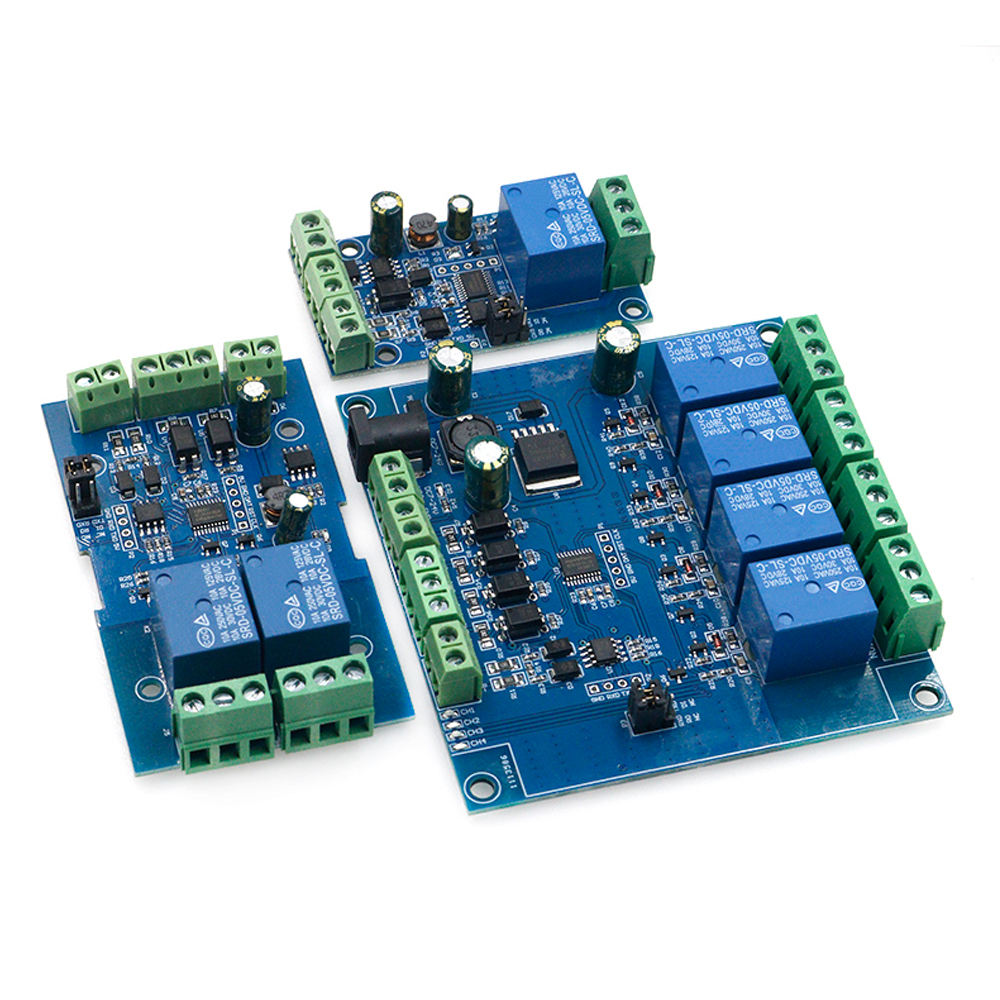
4 Channel
Modbus RTU four-way relay module RS485/TTL UART
4 inputs 4 outputs
Overview
Elsay four-way Modbus relay module is equipped with mature and stable 8-bit MCU and RS485 level communication chip. Using standard MODBUS RTU format RS485 communication protocol, it can realize 4 input signal detection and 4 relay output, which can be used for digital detection or power control occasions.
Features
1. Onboard mature and stable 8bit MCU and MAX485 level conversion chip;
2, Communication protocol: support standard Modbus RTU protocol;
3. Communication interface: support RS485/TTL UART interface;
4. Communication baud rate: 4800/9600/19200, the default is 9600bps, and it supports power-off save;
5. Optocoupler input signal range: DC3.3-30V (this input cannot be used for relay control);
6. Output signal: relay switch signal, support manual, flash off, flash off mode, flash off/flash off delay base is 0.1S, the maximum flash off/flash off time can be set to 0xFFFF*0.1S=6553.5S;
7. Device address: range 1-255, default 255, support power-off save;
8. The baud rate, input signal, relay status, and device address can be read using software/commands;
9. There are 4 5V, 10A/250V AC 10A/30V DC relays on board, which can be activated continuously for 100,000 times, with diode effusion protection, and short response time;
10. On-board relay switch indicator;
11. Power supply voltage: DC7-24V, support DC socket/5.08mm terminal power supply, with input anti-reverse protection;
Hardware introduction and description
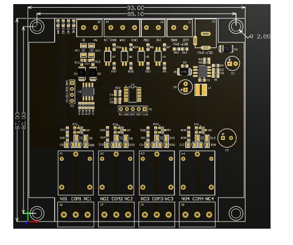
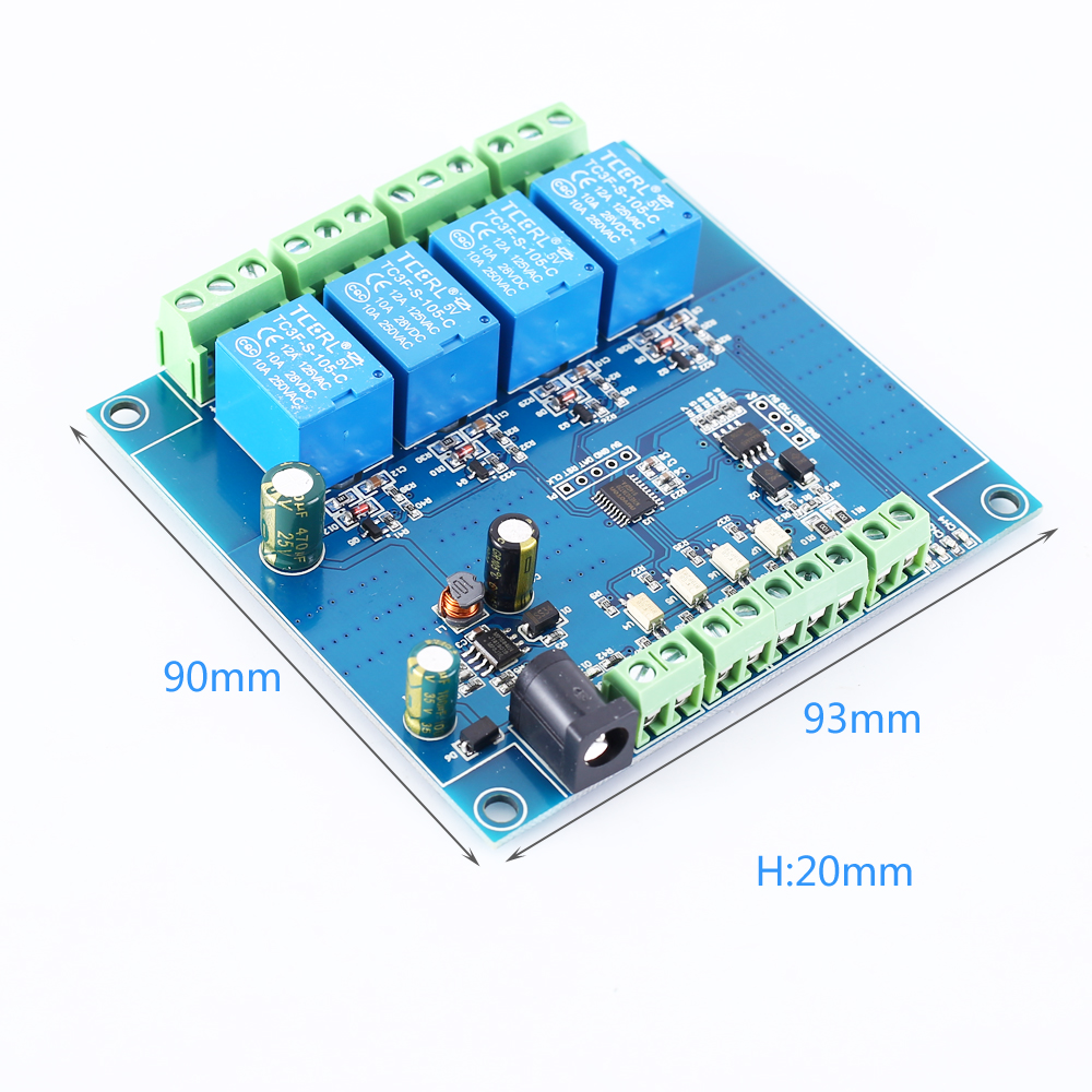
1. Board size
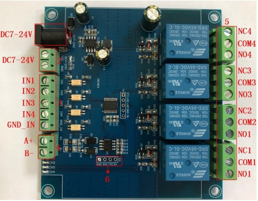
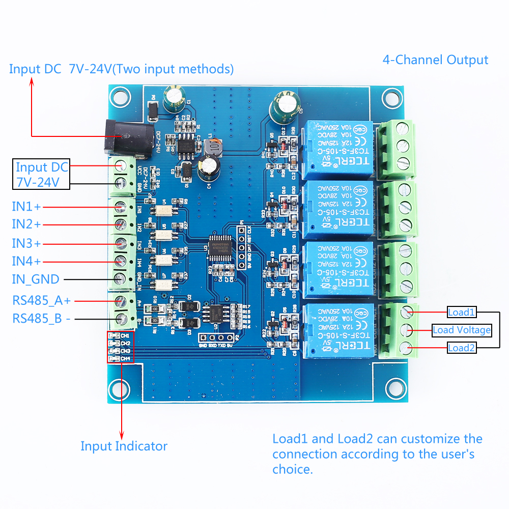
2. Interface introduction
1. DC-005 socket: DC7-24V power input socket;
2. VCC, GND: DC7-24V 5.08mm power input terminal;
3. DC3.3-30V optocoupler signal input:
IN1: Channel 1 positive
IN2: Channel 2 positive
IN3: Channel 3 positive
IN4: Channel 4 positive
GND_IN: Common terminal negative
4. A+, B-: RS485 communication interface, A+, B- are respectively connected to A+, B- of the external control terminal;
5. Relay switch signal output:
NC: Normally closed terminal, the relay is short-connected with COM before it is closed, and it is suspended after it is closed;
COM: public end;
NO: Normally open end, the relay is suspended before closing, and shorted to COM after closing.
6, GND, RXD, TXD: TTL level UART communication interface, GND, RXD, TXD are respectively connected to GND, TXD, RXD of the external control terminal;
Product Parameters:
1>.Item name: 4CH Modbus Relay Module
2>.Work voltage:DC 7V~24V
3>.Baud rate:4800/9600/19600bps(default 9600bps)
4>.Optocoupler input signal:DC 3.3V~30V
5>.Set address:1~255
6>.Relay contorl mode: ON/OFF,Delay_ON,Delay_OFF mode
7>.Delay time: 0~6553.5s
8>.Load: AC 250V 10A or DC 28V 10A
9>.Protocol:Modbus RTU
10>.Interface:RS485/TTL UART
11>.Control channel: 4channel
12>.Operating Temperature:-20℃~85℃
13>.Operating Humidity:5%~95%RH
14>.Module Size:93*90*20mm
Modbus RTU Command:
1>.Suppose the device address is 0xFF so return 00 10 00 00 00 01 02 00 FF EB 80 and the 9th btye is device address.
2>.Turn ON CH_1 Relay(Normal Mode):
Send: FF 05 00 00 FF 00 99 E4
Return: FF 05 00 00 FF 00 99 E4
Note_1:The 3rd and 4th byte are relay addresses.So it can be 0x0000,0x0001,0x0002,0x0003.
Note_2:The 5th and 6th byte are relay data.0xFF00 means turn ON relay and 0x0000 means turn OFF relay.
3>.Turn OFF CH_1 Relay(Normal Mode):
Send: FF 05 00 00 00 00 D8 14
Return: FF 05 00 00 00 00 D8 14
4>.Turn ON CH_2 Relay(Normal Mode):
Send: FF 05 00 01 FF 00 C8 24
Return: FF 05 00 01 FF 00 C8 24
5>.Turn OFF CH_2 Relay(Normal Mode):
Send: FF 05 00 01 00 00 89 D4
Return: FF 05 00 01 00 00 89 D4
6>.Turn ON All relays:
Send: FF 0F 00 00 00 08 01 FF 30 1D
Return: FF 0F 00 00 00 08 41 D3
7>.Turn OFF All relays:
Send: FF 0F 00 00 00 08 01 00 70 5D
Return: FF 0F 00 00 00 08 41 D3
8>.Set device address to 0x01:
Send: 00 10 00 00 00 01 02 00 01 6A 00
Return: 00 10 00 00 00 01 02 00 01 6A 00
Note: The 9th btye is device address.
9>.Set device address to 0xFF:
Send: 00 10 00 00 00 01 02 00 FF EB 80
Return: 00 10 00 00 00 01 02 00 FF EB 80
10>.Read device address:
Send: 00 03 00 00 00 01 85 DB
Return: 00 03 02 00 FF C5 C4
Note: The 5th btye is device address.
11>.Read relay status:
Send: FF 01 00 00 00 08 28 12
Return: FF 01 01 01 A1 A0
Note:The 4th means which one relay.0 means OFF and 1 means ON.
12>.Read optocoupler input staturs:
Send: FF 02 00 00 00 08 6C 12
Return: FF 02 01 01 51 A0
Note:The 4th means which one input.0 means low level signal input and 1 means high level signal input.
13>.Set baud rate 4800bps:
Send: FF 10 03 E9 00 01 02 00 02 4A 0C
Return: FF 10 03 E9 00 01 C5 A7
Note:The 9th btye is baud rate value.0x02 is 4800bps.0x03 is 9600bps.0x04 is 19200bps.
14>.Set baud rate 9600bps:
Send: FF 10 03 E9 00 01 02 00 03 8B CC
Return: FF 10 03 E9 00 01 C5 A7
15>.Set baud rate 19200bps:
Send: FF 10 03 E9 00 01 02 00 04 CA 0E
Return: FF 10 03 E9 00 01 C5 A7
16>.Turn ON CH_1 Relay(2S Flashing Mode):
Send: FF 10 00 03 00 02 04 00 04 00 14 C5 9F
Return: FF 10 00 03 00 02 A4 16
Note_1:The 3rd and 4th byte are relay addresses.So CH1~CH4 can be 0x0003,0x0008,0x000D,0x0012.
Note_2:The 10th and 11th byte are delay time in second.The minimum delay time is 0.1s.Relay will OFF after delay time.So the delay time in this command is : 0x0014*0.1=2S.
17>.Turn OFF CH_1 Relay(3S Flashing Mode):
Send: FF 10 00 03 00 02 04 00 02 00 1E A5 99
Return: FF 10 00 03 00 02 A4 16
Note:Relay will ON after delay time.So the delay time in this command is : 0x001E*0.1=3S.
Package Include:
1PC 4CH Modbus Relay Module


1 Channel
Single Modbus relay module is equipped with mature and stable 8-bit MCU and
RS485 level communication chip. RS485 communication using standard MODBUS RTU format
Communication protocol, which can realize 1 optical coupler input signal detection and 1 relay output, which can be used for digital
Word quantity detection or power control occasions.
Product parameter
1. Onboard mature and stable 8bit MCU and MAX485 level conversion chip
2. Communication protocol: support standard Modbus RTU protocol
3. Communication interface: support RS485/TTL UART interface
4. Communication baud rate: 4800/9600/19200, default 9600bps, support power-off save
6. Optocoupler input signal range: DC3.3-30V (this input cannot be used for relay control)
7. Output signal: relay switch signal, support manual, flash off, flash off mode, flash off/flash
The base number of the time delay is 0.1S, and the maximum flash-off/flash-off time can be set as
0xFFFF*0.1S=65535*0.1S=6553.5S
8. Device address: range 1-255, default 255, support power-off save
9. Onboard 1 way 5V, 10A/250V AC 10A/30V DC relay, can suck continuously
100,000 times, with diode effusion protection, short response time
10. On-board relay switch indicator
11.Supply voltage: DC7-24V, with input anti-reverse connection protection
RS485 level communication chip. RS485 communication using standard MODBUS RTU format
Communication protocol, which can realize 1 optical coupler input signal detection and 1 relay output, which can be used for digital
Word quantity detection or power control occasions.
Product parameter
1. Onboard mature and stable 8bit MCU and MAX485 level conversion chip
2. Communication protocol: support standard Modbus RTU protocol
3. Communication interface: support RS485/TTL UART interface
4. Communication baud rate: 4800/9600/19200, default 9600bps, support power-off save
6. Optocoupler input signal range: DC3.3-30V (this input cannot be used for relay control)
7. Output signal: relay switch signal, support manual, flash off, flash off mode, flash off/flash
The base number of the time delay is 0.1S, and the maximum flash-off/flash-off time can be set as
0xFFFF*0.1S=65535*0.1S=6553.5S
8. Device address: range 1-255, default 255, support power-off save
9. Onboard 1 way 5V, 10A/250V AC 10A/30V DC relay, can suck continuously
100,000 times, with diode effusion protection, short response time
10. On-board relay switch indicator
11.Supply voltage: DC7-24V, with input anti-reverse connection protection
Package included:
DC 7-24V Relay Module RS485/TTL1 Input And Output With Anti-reverse Protection
2 Channel
Description:
Dual ModbSU relay module is equipped with mature and stable 8-bit MCU and
RS485 level communication chip. RS485 communication using standard MODBUS RTU format
Communication protocol, can realize 2 input signal detection, 2 relay output, can be used for digital
In the case of volume detection or power control.
Dual ModbSU relay module is equipped with mature and stable 8-bit MCU and
RS485 level communication chip. RS485 communication using standard MODBUS RTU format
Communication protocol, can realize 2 input signal detection, 2 relay output, can be used for digital
In the case of volume detection or power control.
Product parameter
1. Onboard mature and stable 8bit MCU and MAX485 level conversion chip
2. Communication protocol: support standard Modbus RTU protocol
3. Communication interface: support RS485/TTL UART interface
4. Communication baud rate: 4800/9600/19200, default 9600bps, support power-off save
6. Optocoupler input signal range: DC3.3-30V (this input cannot be used for relay control)
7. Output signal: relay switch signal, support manual, flash off, flash off mode, flash off/flash
The base of the delay time is 0.1S, and the maximum flash-off/flash-off time can be set as
0xFFFF*0.1S-65535*0.1S=6553.5S
8. Device address: range 1-255, default 255, support power-off save
9. Onboard 1 way 5V, 10A/250V AC 10A/30V DC relay, can suck continuously
100,000 times, with diode effusion protection, short response time
10. On-board relay switch indicator
11.Supply voltage: DC7-24V, with input anti-reverse connection protection
1. Onboard mature and stable 8bit MCU and MAX485 level conversion chip
2. Communication protocol: support standard Modbus RTU protocol
3. Communication interface: support RS485/TTL UART interface
4. Communication baud rate: 4800/9600/19200, default 9600bps, support power-off save
6. Optocoupler input signal range: DC3.3-30V (this input cannot be used for relay control)
7. Output signal: relay switch signal, support manual, flash off, flash off mode, flash off/flash
The base of the delay time is 0.1S, and the maximum flash-off/flash-off time can be set as
0xFFFF*0.1S-65535*0.1S=6553.5S
8. Device address: range 1-255, default 255, support power-off save
9. Onboard 1 way 5V, 10A/250V AC 10A/30V DC relay, can suck continuously
100,000 times, with diode effusion protection, short response time
10. On-board relay switch indicator
11.Supply voltage: DC7-24V, with input anti-reverse connection protection
Package Include:
1x DC 7-24V Dual Channel Relay Module Switch Input And Output RS485/TTL
4 Channel
Modbus RTU four-way relay module RS485/TTL UART
4 inputs 4 outputs
Overview
Elsay four-way Modbus relay module is equipped with mature and stable 8-bit MCU and RS485 level communication chip. Using standard MODBUS RTU format RS485 communication protocol, it can realize 4 input signal detection and 4 relay output, which can be used for digital detection or power control occasions.
Features
1. Onboard mature and stable 8bit MCU and MAX485 level conversion chip;
2, Communication protocol: support standard Modbus RTU protocol;
3. Communication interface: support RS485/TTL UART interface;
4. Communication baud rate: 4800/9600/19200, the default is 9600bps, and it supports power-off save;
5. Optocoupler input signal range: DC3.3-30V (this input cannot be used for relay control);
6. Output signal: relay switch signal, support manual, flash off, flash off mode, flash off/flash off delay base is 0.1S, the maximum flash off/flash off time can be set to 0xFFFF*0.1S=6553.5S;
7. Device address: range 1-255, default 255, support power-off save;
8. The baud rate, input signal, relay status, and device address can be read using software/commands;
9. There are 4 5V, 10A/250V AC 10A/30V DC relays on board, which can be activated continuously for 100,000 times, with diode effusion protection, and short response time;
10. On-board relay switch indicator;
11. Power supply voltage: DC7-24V, support DC socket/5.08mm terminal power supply, with input anti-reverse protection;
4 inputs 4 outputs
Overview
Elsay four-way Modbus relay module is equipped with mature and stable 8-bit MCU and RS485 level communication chip. Using standard MODBUS RTU format RS485 communication protocol, it can realize 4 input signal detection and 4 relay output, which can be used for digital detection or power control occasions.
Features
1. Onboard mature and stable 8bit MCU and MAX485 level conversion chip;
2, Communication protocol: support standard Modbus RTU protocol;
3. Communication interface: support RS485/TTL UART interface;
4. Communication baud rate: 4800/9600/19200, the default is 9600bps, and it supports power-off save;
5. Optocoupler input signal range: DC3.3-30V (this input cannot be used for relay control);
6. Output signal: relay switch signal, support manual, flash off, flash off mode, flash off/flash off delay base is 0.1S, the maximum flash off/flash off time can be set to 0xFFFF*0.1S=6553.5S;
7. Device address: range 1-255, default 255, support power-off save;
8. The baud rate, input signal, relay status, and device address can be read using software/commands;
9. There are 4 5V, 10A/250V AC 10A/30V DC relays on board, which can be activated continuously for 100,000 times, with diode effusion protection, and short response time;
10. On-board relay switch indicator;
11. Power supply voltage: DC7-24V, support DC socket/5.08mm terminal power supply, with input anti-reverse protection;
Hardware introduction and description
1. Board size
2. Interface introduction
1. DC-005 socket: DC7-24V power input socket;
2. VCC, GND: DC7-24V 5.08mm power input terminal;
3. DC3.3-30V optocoupler signal input:
IN1: Channel 1 positive
IN2: Channel 2 positive
IN3: Channel 3 positive
IN4: Channel 4 positive
GND_IN: Common terminal negative
4. A+, B-: RS485 communication interface, A+, B- are respectively connected to A+, B- of the external control terminal;
5. Relay switch signal output:
NC: Normally closed terminal, the relay is short-connected with COM before it is closed, and it is suspended after it is closed;
COM: public end;
NO: Normally open end, the relay is suspended before closing, and shorted to COM after closing.
6, GND, RXD, TXD: TTL level UART communication interface, GND, RXD, TXD are respectively connected to GND, TXD, RXD of the external control terminal;
2. VCC, GND: DC7-24V 5.08mm power input terminal;
3. DC3.3-30V optocoupler signal input:
IN1: Channel 1 positive
IN2: Channel 2 positive
IN3: Channel 3 positive
IN4: Channel 4 positive
GND_IN: Common terminal negative
4. A+, B-: RS485 communication interface, A+, B- are respectively connected to A+, B- of the external control terminal;
5. Relay switch signal output:
NC: Normally closed terminal, the relay is short-connected with COM before it is closed, and it is suspended after it is closed;
COM: public end;
NO: Normally open end, the relay is suspended before closing, and shorted to COM after closing.
6, GND, RXD, TXD: TTL level UART communication interface, GND, RXD, TXD are respectively connected to GND, TXD, RXD of the external control terminal;
Product Parameters:
1>.Item name: 4CH Modbus Relay Module
2>.Work voltage:DC 7V~24V
3>.Baud rate:4800/9600/19600bps(default 9600bps)
4>.Optocoupler input signal:DC 3.3V~30V
5>.Set address:1~255
6>.Relay contorl mode: ON/OFF,Delay_ON,Delay_OFF mode
7>.Delay time: 0~6553.5s
8>.Load: AC 250V 10A or DC 28V 10A
9>.Protocol:Modbus RTU
10>.Interface:RS485/TTL UART
11>.Control channel: 4channel
12>.Operating Temperature:-20℃~85℃
13>.Operating Humidity:5%~95%RH
14>.Module Size:93*90*20mm
Modbus RTU Command:
1>.Suppose the device address is 0xFF so return 00 10 00 00 00 01 02 00 FF EB 80 and the 9th btye is device address.
2>.Turn ON CH_1 Relay(Normal Mode):
Send: FF 05 00 00 FF 00 99 E4
Return: FF 05 00 00 FF 00 99 E4
Note_1:The 3rd and 4th byte are relay addresses.So it can be 0x0000,0x0001,0x0002,0x0003.
Note_2:The 5th and 6th byte are relay data.0xFF00 means turn ON relay and 0x0000 means turn OFF relay.
3>.Turn OFF CH_1 Relay(Normal Mode):
Send: FF 05 00 00 00 00 D8 14
Return: FF 05 00 00 00 00 D8 14
4>.Turn ON CH_2 Relay(Normal Mode):
Send: FF 05 00 01 FF 00 C8 24
Return: FF 05 00 01 FF 00 C8 24
5>.Turn OFF CH_2 Relay(Normal Mode):
Send: FF 05 00 01 00 00 89 D4
Return: FF 05 00 01 00 00 89 D4
6>.Turn ON All relays:
Send: FF 0F 00 00 00 08 01 FF 30 1D
Return: FF 0F 00 00 00 08 41 D3
7>.Turn OFF All relays:
Send: FF 0F 00 00 00 08 01 00 70 5D
Return: FF 0F 00 00 00 08 41 D3
8>.Set device address to 0x01:
Send: 00 10 00 00 00 01 02 00 01 6A 00
Return: 00 10 00 00 00 01 02 00 01 6A 00
Note: The 9th btye is device address.
9>.Set device address to 0xFF:
Send: 00 10 00 00 00 01 02 00 FF EB 80
Return: 00 10 00 00 00 01 02 00 FF EB 80
10>.Read device address:
Send: 00 03 00 00 00 01 85 DB
Return: 00 03 02 00 FF C5 C4
Note: The 5th btye is device address.
11>.Read relay status:
Send: FF 01 00 00 00 08 28 12
Return: FF 01 01 01 A1 A0
Note:The 4th means which one relay.0 means OFF and 1 means ON.
12>.Read optocoupler input staturs:
Send: FF 02 00 00 00 08 6C 12
Return: FF 02 01 01 51 A0
Note:The 4th means which one input.0 means low level signal input and 1 means high level signal input.
13>.Set baud rate 4800bps:
Send: FF 10 03 E9 00 01 02 00 02 4A 0C
Return: FF 10 03 E9 00 01 C5 A7
Note:The 9th btye is baud rate value.0x02 is 4800bps.0x03 is 9600bps.0x04 is 19200bps.
14>.Set baud rate 9600bps:
Send: FF 10 03 E9 00 01 02 00 03 8B CC
Return: FF 10 03 E9 00 01 C5 A7
15>.Set baud rate 19200bps:
Send: FF 10 03 E9 00 01 02 00 04 CA 0E
Return: FF 10 03 E9 00 01 C5 A7
16>.Turn ON CH_1 Relay(2S Flashing Mode):
Send: FF 10 00 03 00 02 04 00 04 00 14 C5 9F
Return: FF 10 00 03 00 02 A4 16
Note_1:The 3rd and 4th byte are relay addresses.So CH1~CH4 can be 0x0003,0x0008,0x000D,0x0012.
Note_2:The 10th and 11th byte are delay time in second.The minimum delay time is 0.1s.Relay will OFF after delay time.So the delay time in this command is : 0x0014*0.1=2S.
17>.Turn OFF CH_1 Relay(3S Flashing Mode):
Send: FF 10 00 03 00 02 04 00 02 00 1E A5 99
Return: FF 10 00 03 00 02 A4 16
Note:Relay will ON after delay time.So the delay time in this command is : 0x001E*0.1=3S.
Package Include:
1PC 4CH Modbus Relay Module
1>.Item name: 4CH Modbus Relay Module
2>.Work voltage:DC 7V~24V
3>.Baud rate:4800/9600/19600bps(default 9600bps)
4>.Optocoupler input signal:DC 3.3V~30V
5>.Set address:1~255
6>.Relay contorl mode: ON/OFF,Delay_ON,Delay_OFF mode
7>.Delay time: 0~6553.5s
8>.Load: AC 250V 10A or DC 28V 10A
9>.Protocol:Modbus RTU
10>.Interface:RS485/TTL UART
11>.Control channel: 4channel
12>.Operating Temperature:-20℃~85℃
13>.Operating Humidity:5%~95%RH
14>.Module Size:93*90*20mm
Modbus RTU Command:
1>.Suppose the device address is 0xFF so return 00 10 00 00 00 01 02 00 FF EB 80 and the 9th btye is device address.
2>.Turn ON CH_1 Relay(Normal Mode):
Send: FF 05 00 00 FF 00 99 E4
Return: FF 05 00 00 FF 00 99 E4
Note_1:The 3rd and 4th byte are relay addresses.So it can be 0x0000,0x0001,0x0002,0x0003.
Note_2:The 5th and 6th byte are relay data.0xFF00 means turn ON relay and 0x0000 means turn OFF relay.
3>.Turn OFF CH_1 Relay(Normal Mode):
Send: FF 05 00 00 00 00 D8 14
Return: FF 05 00 00 00 00 D8 14
4>.Turn ON CH_2 Relay(Normal Mode):
Send: FF 05 00 01 FF 00 C8 24
Return: FF 05 00 01 FF 00 C8 24
5>.Turn OFF CH_2 Relay(Normal Mode):
Send: FF 05 00 01 00 00 89 D4
Return: FF 05 00 01 00 00 89 D4
6>.Turn ON All relays:
Send: FF 0F 00 00 00 08 01 FF 30 1D
Return: FF 0F 00 00 00 08 41 D3
7>.Turn OFF All relays:
Send: FF 0F 00 00 00 08 01 00 70 5D
Return: FF 0F 00 00 00 08 41 D3
8>.Set device address to 0x01:
Send: 00 10 00 00 00 01 02 00 01 6A 00
Return: 00 10 00 00 00 01 02 00 01 6A 00
Note: The 9th btye is device address.
9>.Set device address to 0xFF:
Send: 00 10 00 00 00 01 02 00 FF EB 80
Return: 00 10 00 00 00 01 02 00 FF EB 80
10>.Read device address:
Send: 00 03 00 00 00 01 85 DB
Return: 00 03 02 00 FF C5 C4
Note: The 5th btye is device address.
11>.Read relay status:
Send: FF 01 00 00 00 08 28 12
Return: FF 01 01 01 A1 A0
Note:The 4th means which one relay.0 means OFF and 1 means ON.
12>.Read optocoupler input staturs:
Send: FF 02 00 00 00 08 6C 12
Return: FF 02 01 01 51 A0
Note:The 4th means which one input.0 means low level signal input and 1 means high level signal input.
13>.Set baud rate 4800bps:
Send: FF 10 03 E9 00 01 02 00 02 4A 0C
Return: FF 10 03 E9 00 01 C5 A7
Note:The 9th btye is baud rate value.0x02 is 4800bps.0x03 is 9600bps.0x04 is 19200bps.
14>.Set baud rate 9600bps:
Send: FF 10 03 E9 00 01 02 00 03 8B CC
Return: FF 10 03 E9 00 01 C5 A7
15>.Set baud rate 19200bps:
Send: FF 10 03 E9 00 01 02 00 04 CA 0E
Return: FF 10 03 E9 00 01 C5 A7
16>.Turn ON CH_1 Relay(2S Flashing Mode):
Send: FF 10 00 03 00 02 04 00 04 00 14 C5 9F
Return: FF 10 00 03 00 02 A4 16
Note_1:The 3rd and 4th byte are relay addresses.So CH1~CH4 can be 0x0003,0x0008,0x000D,0x0012.
Note_2:The 10th and 11th byte are delay time in second.The minimum delay time is 0.1s.Relay will OFF after delay time.So the delay time in this command is : 0x0014*0.1=2S.
17>.Turn OFF CH_1 Relay(3S Flashing Mode):
Send: FF 10 00 03 00 02 04 00 02 00 1E A5 99
Return: FF 10 00 03 00 02 A4 16
Note:Relay will ON after delay time.So the delay time in this command is : 0x001E*0.1=3S.
Package Include:
1PC 4CH Modbus Relay Module


Am 01.09.2023 hat der Verkäufer die folgenden Angaben hinzugefügt: