This item includes:
4PCS Nema 34 Stepper Motor with 1090oz-in holding torque, 5.6A,99mm Length, 14mm single flat shaft.
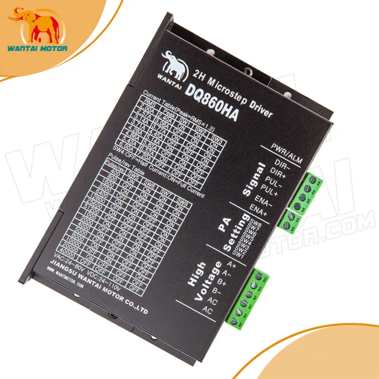
4PCS Stepper Driver DQ860HA with 7.8A AC:24~80V DC:24~110V replacing DQ860MA,
4PCS Power Suuply 350W 60V
1PC Breakout Board&1PC DB25 Cable for free
1, Stepper Motor
1 stepper motor:85BYGH450D-008
Electrical Specifications :
Model | Step angel ( °) | Motor Length L(mm) | Rate Voltage (V) | Rate Current (A) | Phase Resistance (Ω) | Phase Inductance (mH) | Holding Torque (N.m) | Lead Wire (NO.) | Rotor Inertia (kg.cm ) | Motor Weight (kg) |
85BYGH450D-008 | 1.8 | 99 | 2.13 | 5.6 | 0.38 | 15 | 7.8 | 4 | 1.7 | 4 |
Introduction:
DQ860HA is a type of two-phase hybrid stepping motor driver, the drive voltage of it is from 24VDC to 80VDC. It is designed for use with 2-phase hybrid stepper motor of all kinds with 57mm to 110mm outside diameter and less than 7.8A phase current. This circuit that it adopts is similar to the circuit of servo control which enables the motor run smoothly almost without noise and vibration. Holding torque when DQ860MA run under high speed is also significantly higher than the other two-phase driver, what’s more, the positioning accuracy is also higher. It is widely used in middle and big size numerical control devices such as curving machine, CNC machine, and computer embroider machine, packing machines and so on.
Features:
² High performance, low price
² Average current control, 2-phase sinusoidal output current drive
² Supply voltage from 24VDC to 110VDC 24VAC-80VAC
² Opto-isolated signal I/O
² Overvoltage, under voltage, overcurrent, phase short circuit protectio
² 14 channels subdivision and automatic idle-current reduction
² 8 channels output phase current setting
² Offline command input terminal
² Motor torque is related to speed, but not related to step/revolution
² High start speed
² High hording torque under high speed
Electrical specification:
Input voltage | 24-80VDC |
Input current | < 6A |
Output current | 2.8A~7.8A |
Consumption | Consumption:80W; Internal Insurance:10A |
Temperature | Working Temperature -10~45℃; Stocking temperature -40℃~70℃ |
Humidity | No condensation, no water droplets |
gas | Prohibition of combustible gases and conductive dust |
weight | 500G |
Pins assignments and description:
Connector Pins Configurations
Pin Function | Details |
PUL +,PUL- | Pulse signal, PUL+ is the positive end of pulses input pin PUL- is the negative end of pulse input pin |
DIR+,DIR- | DIR signal: DIR+ is the positive end of direction input pin DIR- is the negative end of direction input pin |
ENBL+ | Enable signal: ENBL+ is the positive end of direction input pin. This signal is used for enabling/disabling the driver. High level for enabling the driver and low level for disabling the driver. |
ENBL- | ENBL- is the negative end of direction input pin. Usually left unconnected (enabled) |
Function choice ( Using DIP pins to achieve this function)
1) Micro step resolution is set by SW 5,6,7,8 of the DIP switch as shown in the following table:
SW5 | ON | OFF | ON | OFF | ON | OFF | ON | OFF | ON | OFF | ON | OFF | ON | OFF |
SW6 | ON | ON | OFF | OFF | ON | ON | OFF | OFF | ON | ON | OFF | OFF | ON | ON |
SW7 | ON | ON | ON | ON | OFF | OFF | OFF | OFF | ON | ON | ON | ON | OFF | OFF |
SW8 | ON | ON | ON | ON | ON | ON | ON | ON | OFF | OFF | OFF | OFF | OFF | OFF |
PULSE/REV | 400 | 800 | 1600 | 3200 | 6400 | 12800 | 25600 | 51200 | 1000 | 2000 | 5000 | 10000 | 25000 | 50000 |
2) Standstill current setting
SW4 is used for this purpose. OFF meaning that the standstill current is set to be half of the selected dynamic current and ON meaning that standstill is set to be the same as the selected dynamic current.
3) Output current setting:
The first three bits (SW 1, 2, 3)of the DIP switch are used to set the dynamic current. Select a setting
Closest to your motor’s required current
Output current (A) | ||||
SW1 | SW2 | SW3 | PEAK | RMS |
ON | ON | ON | 2.80 | 2.00 |
OFF | ON | ON | 3.50 | 2.50 |
ON | OFF | ON | 4.20 | 3.00 |
OFF | OFF | ON | 4.90 | 3.50 |
ON | ON | OFF | 5.70 | 4.00 |
OFF | ON | OFF | 6.40 | 4.60 |
ON | OFF | OFF | 7.00 | 5.00 |
OFF | OFF | OFF | 7.80 | 5.60 |
4) Semi-flow function:
Semi-flow function is that there is not step pulse after200 ms, the driver output current automatically reduced to 40% of rated output current, which is used to prevent motor heat.
Pins of motor & power:
Motor and power pins | 1 | A+ | Motors wiring | |
2 | A- | |||
3 | B+ | |||
4 | B- | |||
5,6 | DC+ DC- | Power supply | Power supply :DC24-80VDC The peak input current can not up to 6A
|
3.POWER SUPPLY(350W 60V)
350W Single Output Switching Power Supply
AC input range selected by switch.
Protections:short circuit/overload/over voltage/over temperature
100% full load burn-in test
Low cost,high reliability
1 year warranty
Size: 215*115*50mm
Weight:1.05kg
AC input voltage range: 90~132VAC/180~264VAC
AC inrush current: cold start 25A/115V,50A/230V
DC adjustment range:±10% rated output voltage
Overload protection:105%~135%, hiccup mode, auto recovery
Setup,rise,hold up time: 200ms,50ms,20ms/230VAC at full load
Working temperature and humidity:-10℃~+60℃;20%~90 %RH
Model | DC output voltage, Current range | Voltage tolerance | Ripple &Noise | Efficiency |
S-350-60 | 60V,0~5.8A | ±1% | 150mV | 83% |
4. Breakout Board
Set pins according to software as follows:
Output pin: P1,P2,P3,P4,P5,P6,P7,P8,P9,P14,P16,P17.
l P2 – X axis Pulse, P3 – X axis Direction
l P4 – Y axis Pulse, P5 - Y axis Direction
l P6 – Z axis Pulse, P7 – Z axis Direction
l P8 - A axis Pulse, P9 - A axis Direction
l P14 - B axis Pulse, P1- B axis Direction
l P16 - C axis Pulse, P17- C axis Direction
Input pin: P10 ,P11, P12, P13, P15
l Set them for Emergency Stop and X Y Z Limit switch
