
Modbus RTU four-way relay module RS485/TTL UART
4 inputs 4 outputs
I. Overview
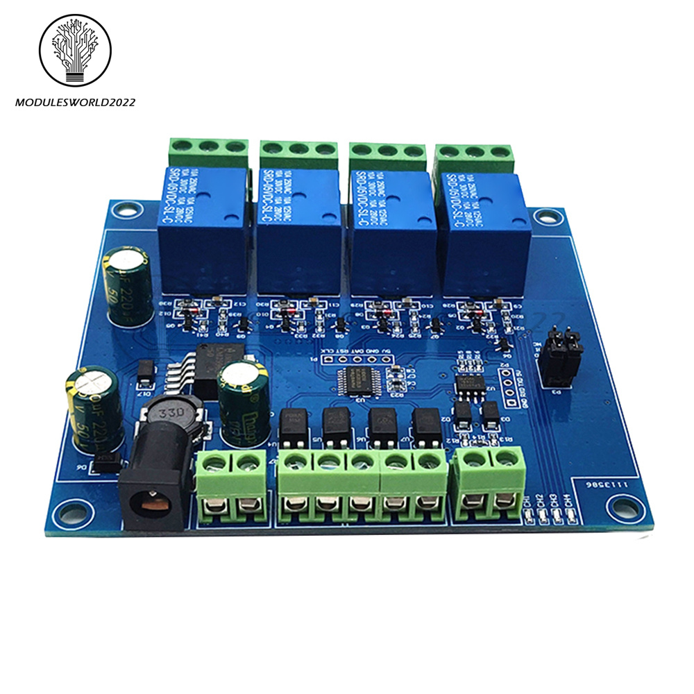
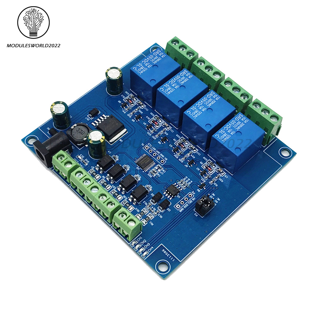
Elsay four-way Modbus relay module is equipped with mature and stable 8-bit MCU and RS485 level communication chip. Using standard MODBUS RTU format RS485 communication protocol, it can realize 4 input signal detection and 4 relay output, which can be used for digital detection or power control occasions.
II. Features
1. Onboard mature and stable 8bit MCU and MAX485 level conversion chip;
2, Communication protocol: support standard Modbus RTU protocol;
3. Communication interface: support RS485/TTL UART interface;
4. Communication baud rate: 4800/9600/19200, the default is 9600bps, and it supports power-off save;
5. Optocoupler input signal range: DC3.3-30V (this input cannot be used for relay control);
6. Output signal: relay switch signal, support manual, flash off, flash off mode, flash off/flash off delay base is 0.1S, the maximum flash off/flash off time can be set to 0xFFFF*0.1S=6553.5S;
7. Device address: range 1-255, default 255, support power-off save;
8. The baud rate, input signal, relay status, and device address can be read using software/commands;
9. There are 4 5V, 10A/250V AC 10A/30V DC relays on board, which can be activated continuously for 100,000 times, with diode effusion protection, and short response time;
10. On-board relay switch indicator;
11. Power supply voltage: DC7-24V, support DC socket/5.08mm terminal power supply, with input anti-reverse protection;
4 inputs 4 outputs
I. Overview
Elsay four-way Modbus relay module is equipped with mature and stable 8-bit MCU and RS485 level communication chip. Using standard MODBUS RTU format RS485 communication protocol, it can realize 4 input signal detection and 4 relay output, which can be used for digital detection or power control occasions.
II. Features
1. Onboard mature and stable 8bit MCU and MAX485 level conversion chip;
2, Communication protocol: support standard Modbus RTU protocol;
3. Communication interface: support RS485/TTL UART interface;
4. Communication baud rate: 4800/9600/19200, the default is 9600bps, and it supports power-off save;
5. Optocoupler input signal range: DC3.3-30V (this input cannot be used for relay control);
6. Output signal: relay switch signal, support manual, flash off, flash off mode, flash off/flash off delay base is 0.1S, the maximum flash off/flash off time can be set to 0xFFFF*0.1S=6553.5S;
7. Device address: range 1-255, default 255, support power-off save;
8. The baud rate, input signal, relay status, and device address can be read using software/commands;
9. There are 4 5V, 10A/250V AC 10A/30V DC relays on board, which can be activated continuously for 100,000 times, with diode effusion protection, and short response time;
10. On-board relay switch indicator;
11. Power supply voltage: DC7-24V, support DC socket/5.08mm terminal power supply, with input anti-reverse protection;
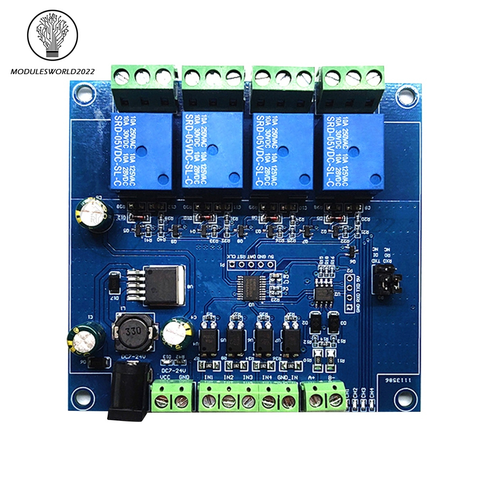
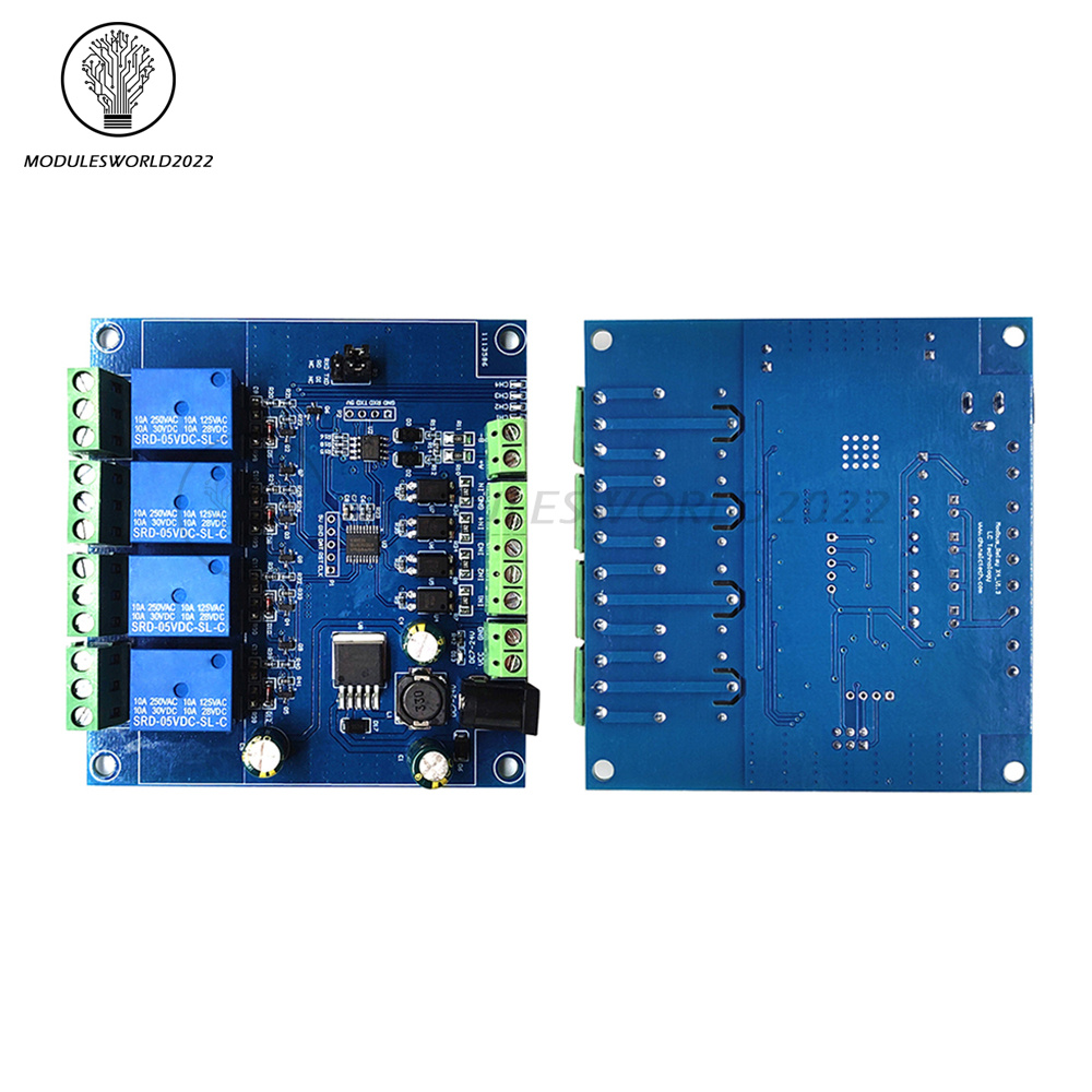
III. Hardware introduction and description
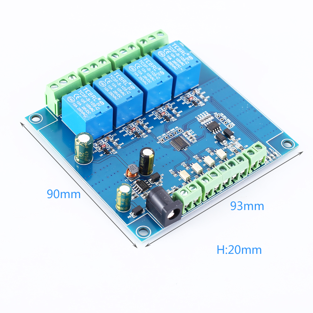
1. Board size
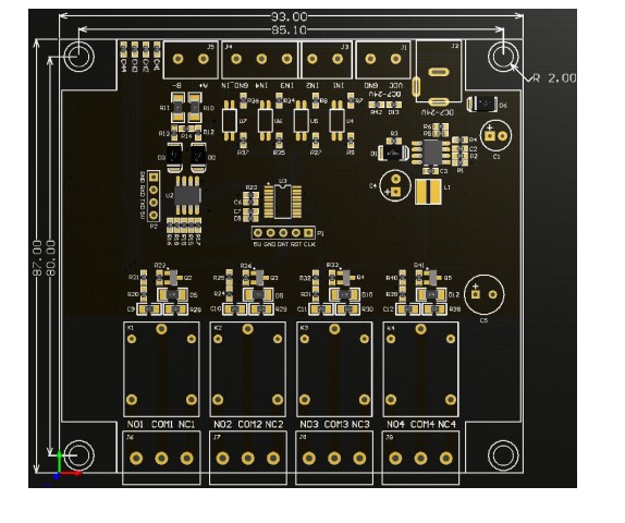
2. Interface introduction
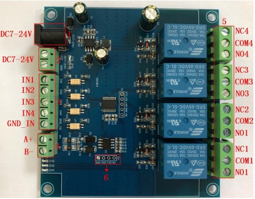
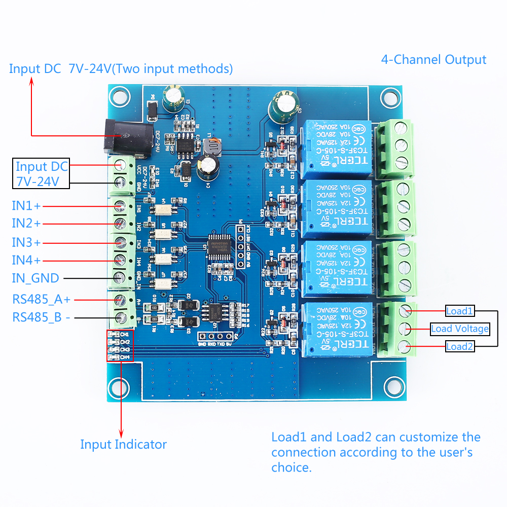
1. DC-005 socket: DC7-24V power input socket;
2. VCC, GND: DC7-24V 5.08mm power input terminal;
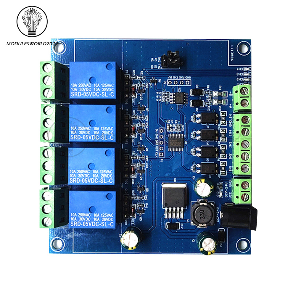
3. DC3.3-30V optocoupler signal input:
IN1: Channel 1 positive
IN2: Channel 2 positive
IN3: Channel 3 positive
IN4: Channel 4 positive
GND_IN: Common terminal negative
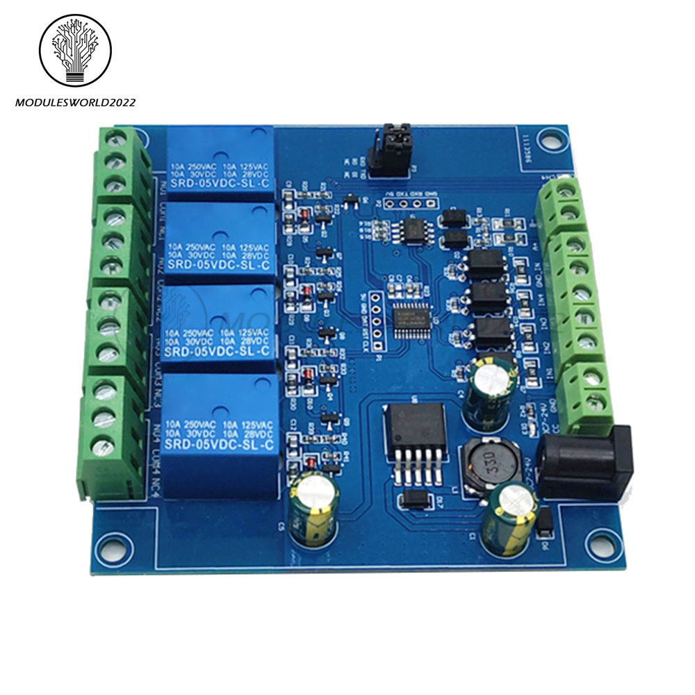
4. A+, B-: RS485 communication interface, A+, B- are respectively connected to A+, B- of the external control terminal;
5. Relay switch signal output:
NC: Normally closed terminal, the relay is short-connected with COM before it is closed, and it is suspended after it is closed;
COM: public end;
NO: Normally open end, the relay is suspended before closing, and shorted to COM after closing.
6, GND, RXD, TXD: TTL level UART communication interface, GND, RXD, TXD are respectively connected to GND, TXD, RXD of the external control terminal;
2. VCC, GND: DC7-24V 5.08mm power input terminal;
3. DC3.3-30V optocoupler signal input:
IN1: Channel 1 positive
IN2: Channel 2 positive
IN3: Channel 3 positive
IN4: Channel 4 positive
GND_IN: Common terminal negative
4. A+, B-: RS485 communication interface, A+, B- are respectively connected to A+, B- of the external control terminal;
5. Relay switch signal output:
NC: Normally closed terminal, the relay is short-connected with COM before it is closed, and it is suspended after it is closed;
COM: public end;
NO: Normally open end, the relay is suspended before closing, and shorted to COM after closing.
6, GND, RXD, TXD: TTL level UART communication interface, GND, RXD, TXD are respectively connected to GND, TXD, RXD of the external control terminal;
IV. Product Parameters:
1>.Item name: 4CH Modbus Relay Module
2>.Work voltage:DC 7V~24V
3>.Baud rate:4800/9600/19600bps(default 9600bps)
4>.Optocoupler input signal:DC 3.3V~30V
5>.Set address:1~255
6>.Relay contorl mode: ON/OFF,Delay_ON,Delay_OFF mode
7>.Delay time: 0~6553.5s
8>.Load: AC 250V 10A or DC 28V 10A
9>.Protocol:Modbus RTU
10>.Interface:RS485/TTL UART
11>.Control channel: 4channel
12>.Operating Temperature:-20℃~85℃
13>.Operating Humidity:5%~95%RH
14>.Module Size:93*90*20mm
V. Modbus RTU Command:
1>.Suppose the device address is 0xFF so return 00 10 00 00 00 01 02 00 FF EB 80 and the 9th btye is device address.
2>.Turn ON CH_1 Relay(Normal Mode):
Send: FF 05 00 00 FF 00 99 E4
Return: FF 05 00 00 FF 00 99 E4
Note_1:The 3rd and 4th byte are relay addresses.So it can be 0x0000,0x0001,0x0002,0x0003.
Note_2:The 5th and 6th byte are relay data.0xFF00 means turn ON relay and 0x0000 means turn OFF relay.
3>.Turn OFF CH_1 Relay(Normal Mode):
Send: FF 05 00 00 00 00 D8 14
Return: FF 05 00 00 00 00 D8 14
4>.Turn ON CH_2 Relay(Normal Mode):
Send: FF 05 00 01 FF 00 C8 24
Return: FF 05 00 01 FF 00 C8 24
5>.Turn OFF CH_2 Relay(Normal Mode):
Send: FF 05 00 01 00 00 89 D4
Return: FF 05 00 01 00 00 89 D4
6>.Turn ON All relays:
Send: FF 0F 00 00 00 08 01 FF 30 1D
Return: FF 0F 00 00 00 08 41 D3
7>.Turn OFF All relays:
Send: FF 0F 00 00 00 08 01 00 70 5D
Return: FF 0F 00 00 00 08 41 D3
8>.Set device address to 0x01:
Send: 00 10 00 00 00 01 02 00 01 6A 00
Return: 00 10 00 00 00 01 02 00 01 6A 00
Note: The 9th btye is device address.
9>.Set device address to 0xFF:
Send: 00 10 00 00 00 01 02 00 FF EB 80
Return: 00 10 00 00 00 01 02 00 FF EB 80
10>.Read device address:
Send: 00 03 00 00 00 01 85 DB
Return: 00 03 02 00 FF C5 C4
Note: The 5th btye is device address.
11>.Read relay status:
Send: FF 01 00 00 00 08 28 12
Return: FF 01 01 01 A1 A0
Note:The 4th means which one relay.0 means OFF and 1 means ON.
12>.Read optocoupler input staturs:
Send: FF 02 00 00 00 08 6C 12
Return: FF 02 01 01 51 A0
Note:The 4th means which one input.0 means low level signal input and 1 means high level signal input.
13>.Set baud rate 4800bps:
Send: FF 10 03 E9 00 01 02 00 02 4A 0C
Return: FF 10 03 E9 00 01 C5 A7
Note:The 9th btye is baud rate value.0x02 is 4800bps.0x03 is 9600bps.0x04 is 19200bps.
14>.Set baud rate 9600bps:
Send: FF 10 03 E9 00 01 02 00 03 8B CC
Return: FF 10 03 E9 00 01 C5 A7
15>.Set baud rate 19200bps:
Send: FF 10 03 E9 00 01 02 00 04 CA 0E
Return: FF 10 03 E9 00 01 C5 A7
16>.Turn ON CH_1 Relay(2S Flashing Mode):
Send: FF 10 00 03 00 02 04 00 04 00 14 C5 9F
Return: FF 10 00 03 00 02 A4 16
Note_1:The 3rd and 4th byte are relay addresses.So CH1~CH4 can be 0x0003,0x0008,0x000D,0x0012.
Note_2:The 10th and 11th byte are delay time in second.The minimum delay time is 0.1s.Relay will OFF after delay time.So the delay time in this command is : 0x0014*0.1=2S.
17>.Turn OFF CH_1 Relay(3S Flashing Mode):
Send: FF 10 00 03 00 02 04 00 02 00 1E A5 99
Return: FF 10 00 03 00 02 A4 16
Note:Relay will ON after delay time.So the delay time in this command is : 0x001E*0.1=3S.
VI. Package Include:
1PC 4CH Modbus Relay Module

Modbus RTU four-way relay module RS485/TTL UART
4 inputs 4 outputs
I. Overview
Elsay four-way Modbus relay module is equipped with mature and stable 8-bit MCU and RS485 level communication chip. Using standard MODBUS RTU format RS485 communication protocol, it can realize 4 input signal detection and 4 relay output, which can be used for digital detection or power control occasions.
II. Features
1. Onboard mature and stable 8bit MCU and MAX485 level conversion chip;
2, Communication protocol: support standard Modbus RTU protocol;
3. Communication interface: support RS485/TTL UART interface;
4. Communication baud rate: 4800/9600/19200, the default is 9600bps, and it supports power-off save;
5. Optocoupler input signal range: DC3.3-30V (this input cannot be used for relay control);
6. Output signal: relay switch signal, support manual, flash off, flash off mode, flash off/flash off delay base is 0.1S, the maximum flash off/flash off time can be set to 0xFFFF*0.1S=6553.5S;
7. Device address: range 1-255, default 255, support power-off save;
8. The baud rate, input signal, relay status, and device address can be read using software/commands;
9. There are 4 5V, 10A/250V AC 10A/30V DC relays on board, which can be activated continuously for 100,000 times, with diode effusion protection, and short response time;
10. On-board relay switch indicator;
11. Power supply voltage: DC7-24V, support DC socket/5.08mm terminal power supply, with input anti-reverse protection;
III. Hardware introduction and description
1. Board size
2. Interface introduction
1. DC-005 socket: DC7-24V power input socket;
2. VCC, GND: DC7-24V 5.08mm power input terminal;
3. DC3.3-30V optocoupler signal input:
IN1: Channel 1 positive
IN2: Channel 2 positive
IN3: Channel 3 positive
IN4: Channel 4 positive
GND_IN: Common terminal negative
4. A+, B-: RS485 communication interface, A+, B- are respectively connected to A+, B- of the external control terminal;
5. Relay switch signal output:
NC: Normally closed terminal, the relay is short-connected with COM before it is closed, and it is suspended after it is closed;
COM: public end;
NO: Normally open end, the relay is suspended before closing, and shorted to COM after closing.
6, GND, RXD, TXD: TTL level UART communication interface, GND, RXD, TXD are respectively connected to GND, TXD, RXD of the external control terminal;
IV. Product Parameters:
1>.Item name: 4CH Modbus Relay Module
2>.Work voltage:DC 7V~24V
3>.Baud rate:4800/9600/19600bps(default 9600bps)
4>.Optocoupler input signal:DC 3.3V~30V
5>.Set address:1~255
6>.Relay contorl mode: ON/OFF,Delay_ON,Delay_OFF mode
7>.Delay time: 0~6553.5s
8>.Load: AC 250V 10A or DC 28V 10A
9>.Protocol:Modbus RTU
10>.Interface:RS485/TTL UART
11>.Control channel: 4channel
12>.Operating Temperature:-20℃~85℃
13>.Operating Humidity:5%~95%RH
14>.Module Size:93*90*20mm
V. Modbus RTU Command:
1>.Suppose the device address is 0xFF so return 00 10 00 00 00 01 02 00 FF EB 80 and the 9th btye is device address.
2>.Turn ON CH_1 Relay(Normal Mode):
Send: FF 05 00 00 FF 00 99 E4
Return: FF 05 00 00 FF 00 99 E4
Note_1:The 3rd and 4th byte are relay addresses.So it can be 0x0000,0x0001,0x0002,0x0003.
Note_2:The 5th and 6th byte are relay data.0xFF00 means turn ON relay and 0x0000 means turn OFF relay.
3>.Turn OFF CH_1 Relay(Normal Mode):
Send: FF 05 00 00 00 00 D8 14
Return: FF 05 00 00 00 00 D8 14
4>.Turn ON CH_2 Relay(Normal Mode):
Send: FF 05 00 01 FF 00 C8 24
Return: FF 05 00 01 FF 00 C8 24
5>.Turn OFF CH_2 Relay(Normal Mode):
Send: FF 05 00 01 00 00 89 D4
Return: FF 05 00 01 00 00 89 D4
6>.Turn ON All relays:
Send: FF 0F 00 00 00 08 01 FF 30 1D
Return: FF 0F 00 00 00 08 41 D3
7>.Turn OFF All relays:
Send: FF 0F 00 00 00 08 01 00 70 5D
Return: FF 0F 00 00 00 08 41 D3
8>.Set device address to 0x01:
Send: 00 10 00 00 00 01 02 00 01 6A 00
Return: 00 10 00 00 00 01 02 00 01 6A 00
Note: The 9th btye is device address.
9>.Set device address to 0xFF:
Send: 00 10 00 00 00 01 02 00 FF EB 80
Return: 00 10 00 00 00 01 02 00 FF EB 80
10>.Read device address:
Send: 00 03 00 00 00 01 85 DB
Return: 00 03 02 00 FF C5 C4
Note: The 5th btye is device address.
11>.Read relay status:
Send: FF 01 00 00 00 08 28 12
Return: FF 01 01 01 A1 A0
Note:The 4th means which one relay.0 means OFF and 1 means ON.
12>.Read optocoupler input staturs:
Send: FF 02 00 00 00 08 6C 12
Return: FF 02 01 01 51 A0
Note:The 4th means which one input.0 means low level signal input and 1 means high level signal input.
13>.Set baud rate 4800bps:
Send: FF 10 03 E9 00 01 02 00 02 4A 0C
Return: FF 10 03 E9 00 01 C5 A7
Note:The 9th btye is baud rate value.0x02 is 4800bps.0x03 is 9600bps.0x04 is 19200bps.
14>.Set baud rate 9600bps:
Send: FF 10 03 E9 00 01 02 00 03 8B CC
Return: FF 10 03 E9 00 01 C5 A7
15>.Set baud rate 19200bps:
Send: FF 10 03 E9 00 01 02 00 04 CA 0E
Return: FF 10 03 E9 00 01 C5 A7
16>.Turn ON CH_1 Relay(2S Flashing Mode):
Send: FF 10 00 03 00 02 04 00 04 00 14 C5 9F
Return: FF 10 00 03 00 02 A4 16
Note_1:The 3rd and 4th byte are relay addresses.So CH1~CH4 can be 0x0003,0x0008,0x000D,0x0012.
Note_2:The 10th and 11th byte are delay time in second.The minimum delay time is 0.1s.Relay will OFF after delay time.So the delay time in this command is : 0x0014*0.1=2S.
17>.Turn OFF CH_1 Relay(3S Flashing Mode):
Send: FF 10 00 03 00 02 04 00 02 00 1E A5 99
Return: FF 10 00 03 00 02 A4 16
Note:Relay will ON after delay time.So the delay time in this command is : 0x001E*0.1=3S.
VI. Package Include:
1PC 4CH Modbus Relay Module
1>.Item name: 4CH Modbus Relay Module
2>.Work voltage:DC 7V~24V
3>.Baud rate:4800/9600/19600bps(default 9600bps)
4>.Optocoupler input signal:DC 3.3V~30V
5>.Set address:1~255
6>.Relay contorl mode: ON/OFF,Delay_ON,Delay_OFF mode
7>.Delay time: 0~6553.5s
8>.Load: AC 250V 10A or DC 28V 10A
9>.Protocol:Modbus RTU
10>.Interface:RS485/TTL UART
11>.Control channel: 4channel
12>.Operating Temperature:-20℃~85℃
13>.Operating Humidity:5%~95%RH
14>.Module Size:93*90*20mm
V. Modbus RTU Command:
1>.Suppose the device address is 0xFF so return 00 10 00 00 00 01 02 00 FF EB 80 and the 9th btye is device address.
2>.Turn ON CH_1 Relay(Normal Mode):
Send: FF 05 00 00 FF 00 99 E4
Return: FF 05 00 00 FF 00 99 E4
Note_1:The 3rd and 4th byte are relay addresses.So it can be 0x0000,0x0001,0x0002,0x0003.
Note_2:The 5th and 6th byte are relay data.0xFF00 means turn ON relay and 0x0000 means turn OFF relay.
3>.Turn OFF CH_1 Relay(Normal Mode):
Send: FF 05 00 00 00 00 D8 14
Return: FF 05 00 00 00 00 D8 14
4>.Turn ON CH_2 Relay(Normal Mode):
Send: FF 05 00 01 FF 00 C8 24
Return: FF 05 00 01 FF 00 C8 24
5>.Turn OFF CH_2 Relay(Normal Mode):
Send: FF 05 00 01 00 00 89 D4
Return: FF 05 00 01 00 00 89 D4
6>.Turn ON All relays:
Send: FF 0F 00 00 00 08 01 FF 30 1D
Return: FF 0F 00 00 00 08 41 D3
7>.Turn OFF All relays:
Send: FF 0F 00 00 00 08 01 00 70 5D
Return: FF 0F 00 00 00 08 41 D3
8>.Set device address to 0x01:
Send: 00 10 00 00 00 01 02 00 01 6A 00
Return: 00 10 00 00 00 01 02 00 01 6A 00
Note: The 9th btye is device address.
9>.Set device address to 0xFF:
Send: 00 10 00 00 00 01 02 00 FF EB 80
Return: 00 10 00 00 00 01 02 00 FF EB 80
10>.Read device address:
Send: 00 03 00 00 00 01 85 DB
Return: 00 03 02 00 FF C5 C4
Note: The 5th btye is device address.
11>.Read relay status:
Send: FF 01 00 00 00 08 28 12
Return: FF 01 01 01 A1 A0
Note:The 4th means which one relay.0 means OFF and 1 means ON.
12>.Read optocoupler input staturs:
Send: FF 02 00 00 00 08 6C 12
Return: FF 02 01 01 51 A0
Note:The 4th means which one input.0 means low level signal input and 1 means high level signal input.
13>.Set baud rate 4800bps:
Send: FF 10 03 E9 00 01 02 00 02 4A 0C
Return: FF 10 03 E9 00 01 C5 A7
Note:The 9th btye is baud rate value.0x02 is 4800bps.0x03 is 9600bps.0x04 is 19200bps.
14>.Set baud rate 9600bps:
Send: FF 10 03 E9 00 01 02 00 03 8B CC
Return: FF 10 03 E9 00 01 C5 A7
15>.Set baud rate 19200bps:
Send: FF 10 03 E9 00 01 02 00 04 CA 0E
Return: FF 10 03 E9 00 01 C5 A7
16>.Turn ON CH_1 Relay(2S Flashing Mode):
Send: FF 10 00 03 00 02 04 00 04 00 14 C5 9F
Return: FF 10 00 03 00 02 A4 16
Note_1:The 3rd and 4th byte are relay addresses.So CH1~CH4 can be 0x0003,0x0008,0x000D,0x0012.
Note_2:The 10th and 11th byte are delay time in second.The minimum delay time is 0.1s.Relay will OFF after delay time.So the delay time in this command is : 0x0014*0.1=2S.
17>.Turn OFF CH_1 Relay(3S Flashing Mode):
Send: FF 10 00 03 00 02 04 00 02 00 1E A5 99
Return: FF 10 00 03 00 02 A4 16
Note:Relay will ON after delay time.So the delay time in this command is : 0x001E*0.1=3S.
VI. Package Include:
1PC 4CH Modbus Relay Module