
Michigan Synth Works F8R 8-Channel Fader Bank Module (black)
8-channel fader bank module
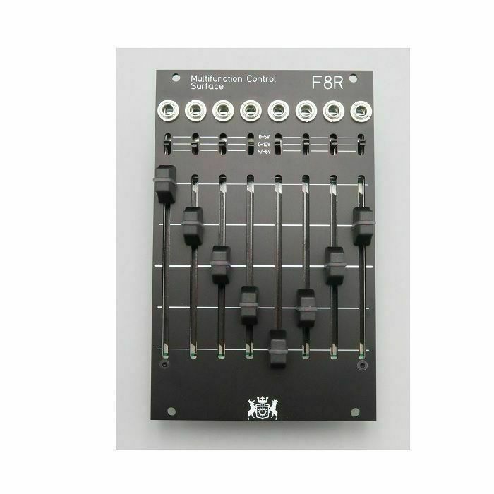
F8R is a 8 channel, 16hp control surface for Eurorack
16HP Width, 20mm Depth
Current Draw: +12V 50 mA, -12V 40 mA
Basic Usage instructions:
Front:
Voltage Select switches: Independent for each channel. Does NOT affect MIDI/I2C data
Slider LED color: To change the LED color, simply remove the cap and rotate the square LED 180s. Do NOT force the LED back in, it should slide in easily, may require wiggling.
Rear:
Power Header: Standard 10pin power cable, there is NO polarity for this connection. It can be connected either way
MIDI Out Header: This is a 4 pin header but only 3 or 2 connections need to be used. To connect to a DIN cable, either GND, 5 (to pin 5, current sink/aka -), and 4 (to pin 4, current source/aka +) should be used. For internal module to module connections, only pin 4 and 5 should be used. The ground pin is only for the shield in a midi cable, it is never connected on a midi input and isnt necessary for the short module to module lengths
I2C Header: 3 pin header to connect to other I2C devices in your rack, this is an unbuffered connection so cable lengths should be as short as possible (20cm/6" recommended). There are 4.7k pull up resistors on this connection
Module Orientation jumpers: There are 3 of these jumpers which determine how the module operates depending on if the jacks are on top or bottom. They will come installed in the position matching your panel but can be changed should you want to flip it. "INV" is Jacks on Top, the white position is jacks on bottom. Changing these jumpers will change the numbering of the faders from left to right (1->8) in both MIDI and I2C and will invert the voltage response (i.e. 10->0V from top to bottom). The jumper is shown in the "jacks on top" position in the pic below. ALL THREE JUMPERS MUST BE IN THE SAME POSITION for the module to operate correctly.
Module Config DIP switch: This allows you to switch between I2C Follower and I2C Leader modes easily. Simply move the switch to the "lead" position and restart the module (you can press the blue reset button once). The other 3 positions are for future expansion and not currently implemented.
Connector for Expander: This connects the F8R to the I/O expander. The cable is attached to the expander. Note the keyway at the top of the part, the connecter will ONLY connect one way
Features
- Long throw LED 60mm faders
- 0-5V, 0-10V, -5 to +5V CV ranges per channel
- Fully analog CV outputs
- I2C communications as master or follower
- I2C mode and addressing easily set by hardware switches. No coding needed
- MIDI header for one output channel on the back of the device
- I2C, MIDI, and CV can be used simultaneously
- Arduino codebase for further customization of midi output/I2C data
- Available expander with additional midi and i2c outs
- Dual Colored LEDs. Red/Green . Red/Blue, Blue/Pink